Free Body Diagram
The free body diagram is a pictorial representation used to analyze the forces acting on a body. The purpose of a free body diagram is to show all the forces acting on a body due to contact with other objects, and/or due to body forces acting on the body (such as gravity or magnetic fields).The free body diagram allows you to set up the problem properly so that you can correctly solve for unknowns such as forces, and acceleration. It allows you to get a “feel” for what’s going on before applying the equations of motion. It is especially important for more complicated problems where it is easy to accidentally forget something if you’re trying to solve the problem just by directly plugging values into equations, without using a visual aid first.
The following general procedure is used when drawing a free body diagram:
• Replace all contact locations with other objects, or supports, with equivalent resultant force and/or moment vectors acting at those locations.
• Account for any constraints, which restrict the motion of the body in some way (e.g. pin joint).
• Body forces (such as gravity) are replaced with equivalent forces passing through the center of mass.
• Assign a coordinate system, in order to solve for the different unknowns in terms of coordinate values. The choice of coordinate system, such as Cartesian, or polar is often based on convenience. In order to accurately relate the forces acting on a body to its acceleration, the coordinate system used must be an inertial reference frame.
• Make any necessary assumptions in order to simplify the solution. For example, a constant friction coefficient can be assumed for determining the friction force acting on a body in contact with a rough surface.
• Sometimes there are multiple bodies interacting with one another, so a free-body diagram must be drawn for each body. This allows for the physical interaction between the bodies to be established, thus allowing the whole system to be solved simultaneously. When drawing the forces acting on pairs of bodies in contact with each other, apply Newton's Third Law.
• If the forces and/or moments acting on the bodies are unknown, assign them directions of your choosing. Make sure you are consistent with the sign convention used. When you solve the equations of motion for a particular problem and you get positive values for the forces and/or moments, this means that they are acting in the direction you assumed, in your free body diagram. On the other hand, if you get negative values for the forces and/or moments, this means that they are acting in the opposite direction that you assumed in your free-body diagram.
• A decision must be made whether the problem can be modeled in one-dimension, two-dimensions, or three-dimensions. This choice often depends on the desired accuracy of the solution and the required effort and time spent to arrive at the solution.
• It’s a good idea to keep the free body diagram as general as possible for those cases where you need to solve for the (changing) position of the bodies over time, and (consequently) the changing values of the forces, velocity, and acceleration of the bodies over time. You do this by setting up kinematics equations that capture every stage of the motion. For example, see physics of a golf swing and trebuchet physics.
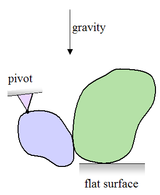
The figure below shows an example of two bodies in contact, with gravity acting downwards and constraints given as shown.
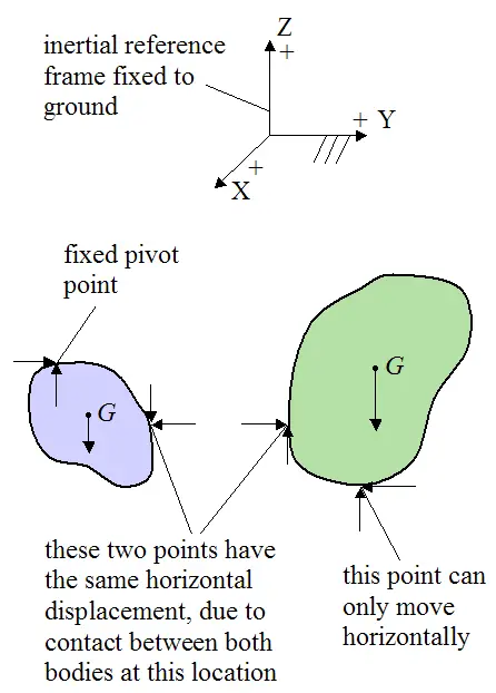
The free body diagram and coordinate frame for this system can be drawn as shown below. The arrows represent forces, and point G represents the center of mass of the bodies:
Return to Dynamics page
Return to Real World Physics Problems home page
Free Newsletter
Subscribe to my free newsletter below. In it I explore physics ideas that seem like science fiction but could become reality in the distant future. I develop these ideas with the help of AI. I will send it out a few times a month.