Rocket Physics
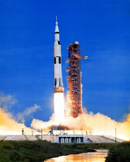
Picture of Saturn V Launch for Apollo 15 Mission. Source: NASA
Rocket physics, in the most basic sense, involves the application of Newton's Laws to a system with variable mass. A rocket has variable mass because its mass decreases over time, as a result of its fuel (propellant) burning off.
A rocket obtains thrust by the principle of action and reaction (Newton's third law). As the rocket propellant ignites, it experiences a very large acceleration and exits the back of the rocket (as exhaust) at a very high velocity. This backwards acceleration of the exhaust exerts a "push" force on the rocket in the opposite direction, causing the rocket to accelerate forward. This is the essential principle behind the physics of rockets, and how rockets work.
The equations of motion of a rocket will be derived next.
Rocket Physics – Equations Of Motion
To find the equations of motion, apply the principle of impulse and momentum to the "system", consisting of rocket and exhaust. In this analysis of the rocket physics we will use Calculus to set up the governing equations. For simplicity, we will assume the rocket is moving in a vacuum, with no gravity, and no air resistance (drag).
To properly analyze the physics, consider the figure below which shows a schematic of a rocket moving in the vertical direction. The two stages, (1) and (2), show the "state" of the system at time t and time t+dt, where dt is a very small (infinitesimal) time step. The system (consisting of rocket and exhaust) is shown as inside the dashed line.

Where:
m is the mass of the rocket (including propellant), at stage (1)
me is the total mass of the rocket exhaust (that has already exited the rocket), at stage (1)
v is the velocity of the rocket, at stage (1)
Je is the linear momentum of the rocket exhaust (that has already exited the rocket), at stage (1). This remains constant between (1) and (2)
dme is the mass of rocket propellant that has exited the rocket (in the form of exhaust), between (1) and (2)
dv is the change in velocity of the rocket, between (1) and (2)
ve is the velocity of the exhaust exiting the rocket, at stage (2)
Note that all velocities are measured with respect to ground (an inertial reference frame).
The sign convention in the vertical direction is as follows: "up" is positive and "down" is negative.
Between (1) and (2), the change in linear momentum in the vertical direction of all the particles in the system, is due to the sum of the external forces in the vertical direction acting on all the particles in the system.
We can express this mathematically using Calculus and the principle of impulse and momentum:
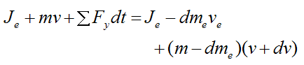
where ΣFy is the sum of the external forces in the vertical direction acting on all the particles in the system (consisting of rocket and exhaust).
Expand the above expression. In the limit as dt→0 we may neglect the "second-order" term dmedv. Divide by dt and simplify. We get
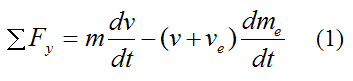
Since the rocket is moving in a vacuum, with no gravity, and no air resistance (drag), then ΣFy = 0 since no external forces are acting on the system. As a result, the above equation becomes
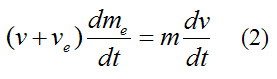
The left side of this equation must represent the thrust acting on the rocket, since a = dv/dt is the acceleration of the rocket, and ΣF = ma (Newton's second law).
Therefore, the thrust T acting on the rocket is equal to
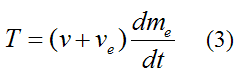
The term v+ve is the velocity of the exhaust gases relative to the rocket. This is approximately constant in rockets. The term dme/dt is the burn rate of rocket propellant.
As the rocket loses mass due to the burning of propellant, its acceleration increases (for a given thrust T). The maximum acceleration is therefore just before all the propellant burns off.
From equation (2),
which becomes
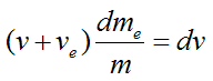
The mass of the ejected rocket exhaust equals the negative of the mass change of the rocket. Thus,
Therefore,
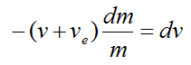
Again, the term v+ve is the velocity of the exhaust gases relative to the rocket, which is approximately constant. For simplicity set u = v+ve.
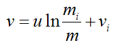
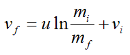
Integrate the above equation using Calculus. We get
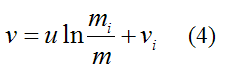
This is a very useful equation coming out of the analysis, shown above. The variables are defined as follows: vi is the initial rocket velocity and mi is the initial rocket mass. The terms v and m are the velocity of the rocket and its mass at any point in time thereafter (respectively). Note that the change in velocity (delta-v) is always the same no matter what the initial velocity vi is. This is a very useful result coming out of the analysis. The fact that delta-v is constant is useful for those instances where powered gravity assist is used to increase the speed of a rocket. By increasing the speed of the rocket at the point when its speed reaches a maximum (during the periapsis stage), the final kinetic energy of the rocket is maximized. This in turn maximizes the final velocity of the rocket. To visualize how this works, imagine dropping a ball onto a floor. We wish to increase the velocity of the ball by a constant amount delta-v at some point during its fall, such that it rebounds off the floor with the maximum possible velocity. It turns out that the point at which to increase the velocity is just before the ball strikes the floor. This maximizes the total energy of the ball (gravitational plus kinetic) which enables it to rebound off the floor with the maximum velocity (and the maximum kinetic energy). This maximum ball velocity is analogous to the maximum possible velocity reached by the rocket at the completion of the gravity assist maneuver. This is known as the Oberth Effect. It is a very useful principle related to rocket physics.
In the following discussion we will look at staging and how it can also be used to obtain greater rocket velocity.
Rocket Physics – Staging
Often times in a space mission, a single rocket cannot carry enough propellant (along with the required tankage, structure, valves, engines and so on) to achieve the necessary mass ratio to achieve the desired final orbital velocity (v). This presents a unique challenge. The only way to overcome this difficulty is by "shedding" unnecessary mass once a certain amount of propellant is burned off. This is accomplished by using different rocket stages and ejecting spent fuel tanks plus associated rocket engines used in those stages, once those stages are completed.
The figure below illustrates how staging works.
Source: NASA
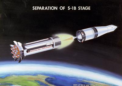
The picture below shows the separation stage of the Saturn V rocket for the Apollo 11 mission.

Source: NASA
The picture below shows the separation stage of the twin rocket boosters of the Space Shuttle.
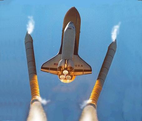
Source: NASA
In the following discussion we will look at rocket efficiency and how it relates to modern (non-rocket powered) aircraft.
Rocket Efficiency
Rockets can accelerate even when the exhaust relative velocity is moving slower than the rocket (meaning ve is in the same direction as the rocket velocity). This differs from propeller engines or air breathing jet engines, which have a limiting speed equal to the speed at which the engine can move the air (while in a stationary position). So when the relative exhaust air velocity is equal to the engine/plane velocity, there is zero thrust. This essentially means that the air is passing through the engine without accelerating, therefore no push force (thrust) is possible. Thus, the physics of rockets is fundamentally different from the physics of propeller engines and jet engines.
Rockets can convert most of the chemical energy of the propellant into mechanical energy (as much as 70%). This is the energy that is converted into motion, of both the rocket and the propellant/exhaust. The rest of the chemical energy of the propellant is lost as waste heat. Rockets are designed to lose as little waste heat as possible. This is accomplished by having the exhaust leave the rocket nozzle at as low a temperature as possible. This maximizes the Carnot efficiency, which maximizes the mechanical energy derived from the propellant (and minimizes the thermal energy lost as waste heat). Carnot efficiency applies to rockets because rocket engines are a type of heat engine, converting some of the initial heat energy of the propellant into mechanical work (and losing the remainder as waste heat). Thus, the physics of rockets is related to heat engine physics.
In the following discussion we will derive the equation of motion for rocket flight in the presence of air resistance (drag) and gravity, such as for rockets flying near the earth's surface.
Flight Near Earth's Surface
The analysis in this section is similar to the previous one, but we are now including the effect of air resistance (drag) and gravity, which is a necessary inclusion for flight near the earth's surface.
For example, let’s consider a rocket moving straight upward against an atmospheric drag force FD and against gravity g (equal to 9.8 m/s2 on earth). The figure below illustrates this.
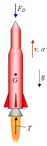
where G is the center of mass of the rocket at the instant shown. The weight of the rocket acts through this point.
From equations (1) and (3) and using the fact that acceleration a = dv/dt we can write the following general equation:
The sum of the external forces acting on the rocket is the gravity force plus the drag force. Thus, from the above equation,
As a result,
This is the general equation of motion accounting for the presence of air resistance (drag) and gravity. Looking closely at this equation, you can see that it is an application of ΣF = ma (Newton’s second law). Note that the mass m of the rocket changes with time (due to propellant burning off), and T is the thrust given from equation (3). An expression for the drag force FD can be found on the page on drag force.
Due to the complexity of the drag term FD, the above equation must be solved numerically to determine the motion of the rocket as a function of time.
Another important consideration is the design of a rocket that experiences minimal atmospheric drag. At high velocities, air resistance is significant. So for purposes of energy efficiency, it is necessary to minimize the atmospheric drag experienced by the rocket, since energy used to overcome drag is energy that is wasted. To minimize drag, rockets are made as aerodynamic as possible, such as with a pointed nose to better cut through the air, as well as using stabilizing fins at the rear of the rocket (near the exhaust), to help maintain steady orientation during flight.
In the following discussion we will take a closer look at thrust.
A Closer Look At Thrust
The thrust given in equation (3) is valid for an optimal nozzle expansion. This assumes that the exhaust gas flows in an ideal manner through the rocket nozzle. But this is not necessarily true in real-life operation. Therefore, in the following analysis we will develop a thrust equation for non-optimal flow of the exhaust gas through the rocket nozzle.
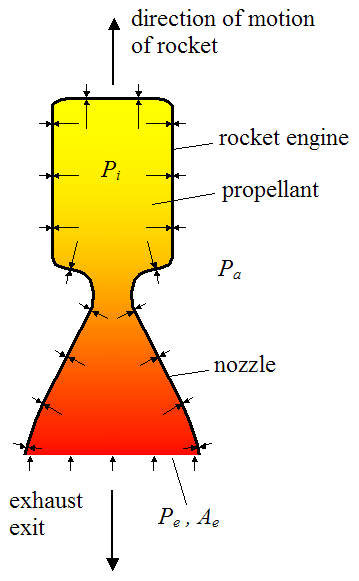
To set up the analysis consider the basic schematic of a rocket engine, shown below.
Where:
Pi is the internal pressure inside the rocket engine (which may vary with location)
Pa is the ambient pressure outside the rocket engine (assumed constant)
Pe is the pressure at the exit plane of the rocket engine nozzle (this is taken as an average pressure along this plane)
Ae is the cross-sectional area of the opening at the nozzle exit plane
The arrows along the top and sides represent the pressure acting on the wall of the rocket engine (inside and outside). The arrows along the bottom represent the pressure acting on the exhaust gas, at the exit plane.
Gravity and air resistance are ignored in this analysis (their effect can be included separately, as shown in the previous section).
Next, isolate the propellant (plus exhaust) inside the rocket engine. It is useful to do this because it allows us to fully account for the contact force between rocket engine wall and propellant (plus exhaust). This contact force can then be related to the thrust experienced by the rocket, as will be shown. The schematic below shows the isolated propellant (plus exhaust). The dashed blue line (along the top and sides) represents the contact interface between the inside wall of the rocket engine and the propellant (plus exhaust). The dashed black line (along the bottom) represents the exit plane of the exhaust gas, upon which the pressure Pe acts.
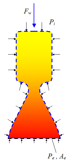
where Fw is the resultant downward force exerted on the propellant (plus exhaust) due to contact with the inside wall of the rocket engine (represented by the dashed blue line). This force is calculated by: (1) Multiplying the local pressure Pi at a point on the inside wall by a differential area on the wall, (2) Using Calculus, integrating over the entire inside wall surface to find the resultant force, and (3) Determining the vertical component of this force (Fw). The details of this calculation are not shown here.
(Note that, due to geometric symmetry of the rocket engine, the resultant force acts in the vertical direction, and there is no sideways component).
Now, sum all the forces acting on the propellant (plus exhaust) and then apply Newton's second law:
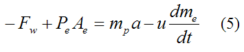
Where:
mp is the mass of the propellant/exhaust inside the rocket engine
a is the acceleration of the rocket engine
u is the velocity of the exhaust gases relative to the rocket, which is approximately constant
dme/dt is the burn rate of the propellant
The right side of the above equation is derived using the same method that was used for deriving equation (1). This is not shown here.
(Note that we are defining "up" as positive and "down" as negative).
Next, isolate the rocket engine, as shown in the schematic below.
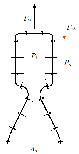
where Frb is the force exerted on the rocket engine by the rocket body.
Now, sum all the forces acting on the rocket engine and then apply Newton's second law:
where mre is the mass of the rocket engine. The term PaAe is the force exerted on the rocket engine due to the ambient pressure acting on the outside of the engine.
Now, by Newton’s third law Frb acting on the rocket body is pointing up (positive). Therefore, by Newton’s second law we can write
where mrb is the mass of the rocket body (which excludes the mass of the rocket engine and the mass of propellant/exhaust inside the rocket engine).
Combine the above two equations and we get
Combine equations (5) and (6) and we get
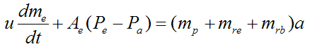
where the term (mp+mre+mrb) is the total mass of the rocket at any point in time. Therefore the left side of the equation must be the thrust acting on the rocket (since F = ma, by Newton's second law).
Thus, the thrust T is
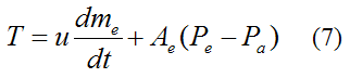
This is the most general equation for thrust coming out of the analysis, shown above. The first term on the right is the momentum thrust term, and the last term on the right is the pressure thrust term due to the difference between the nozzle exit pressure and the ambient pressure. In deriving equation (3) we assumed that Pe = Pa, which means that the pressure thrust term is zero. This is true if there is optimal nozzle expansion and therefore maximum thrust in the rocket nozzle. However, the pressure thrust term is generally small relative to the momentum thrust term.
A subtle point regarding Pe = Pa is that Je (the momentum of the rocket exhaust, described in the first section) remains constant. This is because the pressure force pushing on the exhaust at the rocket nozzle exit (due to the pressure Pe) exactly balances the pressure force pushing on the remainder of the exhaust due to the ambient pressure Pa. Again, we are ignoring gravity and air resistance (drag) in the derivation of equation (3) and (7). To include their effect we simply add their contribution to the thrust force, as shown in the previous section.
The analysis in this section is basically a force and momentum analysis. But to do a complete thrust analysis we would have to look at the thermal and fluid dynamics of the expansion process, as the exhaust gas travels through the rocket nozzle. This analysis (not discussed here) enables one to optimize the engine design plus nozzle geometry such that optimal nozzle expansion is achieved during operation (or as close to it as possible).
The flow of the exhaust gas through the nozzle falls under the category of compressible supersonic flow and its treatment is somewhat complicated.
In the following discussion we will look at the energy consumption of a rocket moving through the air at constant velocity.
Energy Consumption For Rocket Moving At Constant Velocity
An interesting question to ask is, how much energy is used to power a rocket during its flight? One way to answer that is to consider the energy use of a rocket moving at constant velocity, such as through the air. Now, in order for the rocket to move at constant velocity the sum of the forces acting on it must equal zero. For purposes of simplicity let's assume the rocket is traveling horizontally against the force of air resistance (drag), and where gravity has no component in the direction of motion. The figure below illustrates this schematically.
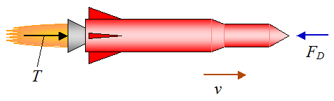
The thrust force T acting on the rocket is equal to the air drag FD, so that T = FD.
Let's say the rocket is moving at a constant horizontal velocity v, and it travels a horizontal distance d. We wish to find the amount of mechanical energy it takes to move the rocket this distance. Note that this is not the same as the total amount of chemical energy in the spent propellant, but rather the amount of energy that was converted into motion. This amount of energy is always less than the total chemical energy in the propellant, due to naturally occurring losses, such as waste heat generated by the rocket engine.
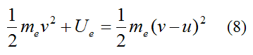
Thus, we must look at the energy used to push the rocket (in the forward direction) and add it to the energy it takes to push the exhaust (in the backward direction). To do this we can apply the principle of work and energy.
For the exhaust gas:
Where:
me is the total mass of the exhaust ejected from the rocket over the flight distance d
u is the velocity of the exhaust gases relative to the rocket, which is approximately constant
Ue is the work required to change the kinetic energy of the rocket propellant/exhaust (ejected from the rocket) over the flight distance d
For the rocket:
Where:
T is the thrust acting on the rocket (this is constant if we assume the burn rate is constant)
Ur is the work required to push the rocket a distance d
Set R = dme/dt (constant burn rate), and assuming optimal nozzle expansion we have
Therefore,
Now, the time t it takes for the rocket to travel a horizontal distance d is

The total mass of exhaust me is
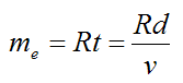
Substitute this into equation (8), then combine equations (8) and (9) to find the total mechanical energy used to propel the rocket over a distance d. Therefore,
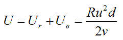
Since T = Ru,
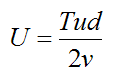
But T = FD, which means we can substitute T with the drag force in the above equation.
Now,
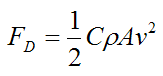
Where:
C is the drag coefficient, which can vary along with the speed of the rocket. But typical values range from 0.4 to 1.0
ρ is the density of the air
A is the projected cross-sectional area of the rocket perpendicular to the flow direction (that is, perpendicular to v)
v is the speed of the rocket relative to the air
Substitute the above equation into the previous equation (for T) and we get
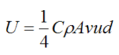
As you can see, the higher the velocity v, the greater the energy required to move the rocket over a distance d, even though the time it takes is less. Furthermore, rockets typically have a large relative exhaust velocity u which makes the energy expenditure large, as evident in the above equation. (The relative exhaust velocity can be in the neighborhood of a few kilometers per second).
This tells us that rockets are inefficient for earth-bound travel, due to the effects of air resistance (drag) and the high relative exhaust velocity u. It is only their high speed that makes them attractive for earth-bound travel, because they can "get there" sooner, which is particularly important for military and weapons applications.
For rockets that are launched into space (such as the Space Shuttle) the density of the air decreases as the altitude of the rocket increases. This decrease, combined with the increase in rocket velocity, means that the drag force will reach a maximum at some altitude (typically several kilometers above the surface of the earth). This maximum drag force must be withstood by the rocket body and as such is an important part of rocket analysis and design.
In the following discussion we will look at the energy consumption of a rocket moving through space.
Energy Consumption For Rocket Moving Through Space
A very useful piece of information in the study of rockets is how much energy a rocket uses for a given increase in speed (delta-v), while traveling in space. This analysis is conveniently simplified somewhat since gravity force and air drag are non-existent. Once again, we are assuming optimal nozzle expansion.
We will need to apply the principle of work and energy to the system (consisting of rocket and propellant/exhaust), to determine the required energy.
The initial kinetic energy of the system is:
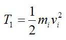
Where:
mi is the initial rocket (plus propellant) mass
vi is the initial rocket (plus propellant) velocity
The final kinetic energy of the rocket is:
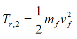
Where:
mf is the final rocket mass
vf is the final rocket velocity
The exhaust gases are assumed to continue traveling at the same velocity as they did upon exiting the rocket. Therefore, the final kinetic energy of the exhaust gases is:

Where:
dme is the infinitesimal mass of rocket propellant that has exited the rocket (in the form of exhaust), over a very small time duration
ve is the velocity of the exhaust exiting the rocket, at stage (2), at a given time
The last term on the right represents an integration, in which you have to sum over all the exhaust particles for the whole burn time.
Therefore, the final kinetic energy of the rocket (plus exhaust) is:
Now, apply the principle of work and energy to all the particles in the system, consisting of rocket and propellant/exhaust:
Substituting the expressions for T1 and T2 into the above equation we get
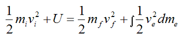
Where:
U is the mechanical energy used by the rocket between initial and final velocity (in other words, for a given delta-v). This amount of energy is less than the total chemical energy in the propellant, due to naturally occurring losses, such as waste heat generated by the rocket engine. U must be solved for in the above equation.
and
and
From equation (4),
where u is the velocity of the exhaust gases relative to the rocket (constant).
Hence,
Note that all velocities are measured with respect to an inertial reference frame.
After a lot of algebra and messy integration we find that,
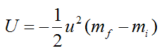
This answer is very nice and compact, and it does not depend on the initial velocity vi. This is perhaps a surprising result coming out of this analysis.
If we want to find the mechanical power P generated by the rocket, differentiate the above expression with respect to time. This gives us
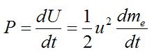
where dme/dt is the burn rate of rocket propellant.
Note that, in the above energy calculations, the rocket does not have to be flying in a straight line. The required energy U is the same regardless of the path taken by the rocket between initial and final velocity. However, it is assumed that any angular rotation of the rocket stays constant (and can therefore be excluded from the energy equation), or it is small enough to be negligible. Thus, the energy bookkeeping only consists of translational rocket velocity.
This concludes the discussion on rocket physics.
Return to Miscellaneous Physics page
Return to Real World Physics Problems home page
Free Newsletter
Subscribe to my free newsletter below. In it I explore physics ideas that seem like science fiction but could become reality in the distant future. I develop these ideas with the help of AI. I will send it out a few times a month.