Low Temperature Stirling Engine
Low temperature Stirling engines are less thermally efficient than high-temperature Stirling engines because of their lower Carnot efficiency. Therefore, they need to be larger in size to produce the same power output. Furthermore, low temperature engines need more heat transfer surface area than high temperature engines. This is because their output power is much more sensitive to the delta-T between the hot/cold source and the working gas. For example, consider a high temperature engine with a hot source temperature of 1000 K and a cold source temperature of 323 K. Now suppose the effective working gas temperature is 950 K and 373 K, at the hot and cold end, respectively. This results in a change in Carnot efficiency from 68% to 61%. Next, consider a low temperature engine with a hot source temperature of 600 K and a cold source temperature of 323 K. Now suppose the effective working gas temperature is 550 K and 373 K, at the hot and cold end, respectively. This results in a change in Carnot efficiency from 46% to 32%. For the high temperature engine, the efficiency dropped 7%, and for the low temperature engine, the efficiency dropped 14% (for the same delta-T, which is equal to 50 K). This means that for low temperature engines, it is more critical to keep the working gas temperature in the hot and cold end as close as possible to the hot and cold source temperature, respectively. Therefore, we must keep delta-T as small as possible in low temperature engines, and this is done by making the heat transfer surface area larger.Delta-T must be kept small while also maintaining the level of heat transfer into and out of the engine. Consider the basic equation for rate of heat transfer, which is: Q = (Surface area)×(overall heat transfer coefficient)×(average delta-T between hot/cold source and working gas). From this equation, one can see that, by keeping delta-T smaller, and increasing surface area, the rate of heat transfer can be maintained (i.e. kept constant).
Low temperature Stirling engines have the advantage of being able to utilize lower-level heat from a variety of sources, such as waste heat from industrial processes, or from solar collectors. A low temperature Stirling engine can run using a hot source temperature between, say, 150 degrees Celsius and 300 degrees Celsius. For example, these heat sources can be used to heat the hot fluid flowing through the hot side heat exchanger of the Stirling engine, shown in the figure below. Low temperature engines producing anywhere from 1 kW to 25 kW have been produced.
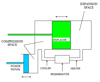
The following is a basic diagram of a low temperature Stirling engine, along with key components labelled. I came up with this design based on a lot of reading and knowing a lot about these engines.
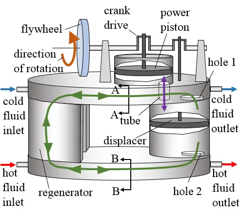
The purple path shown in the first diagram denotes the flow of working gas between the power piston cylinder and the displacer piston cylinder, via the tube shown. The green path denotes the flow of working gas between the compression space and the expansion space (via the heat exchangers and regenerator). Note that there is no mixing of working gas between the two paths.
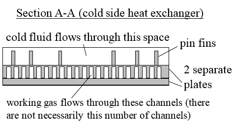
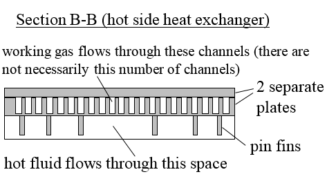
A Closer look at the Heat Exchangers
The following show views of the heat exchanging components of the engine. Below is a top view of the hot and cold side heat exchanger.
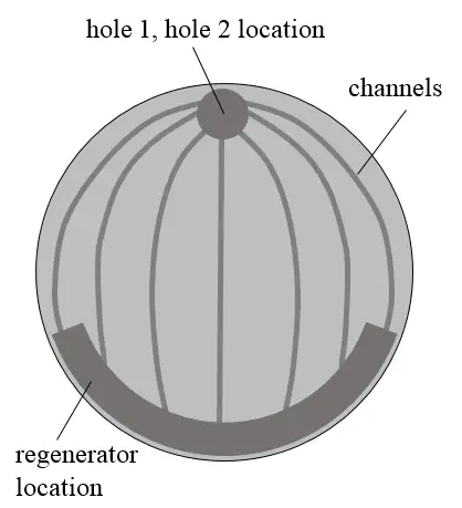
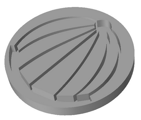
The figure below shows a solid 3D view of the hot and cold side heat exchangers. The channels, hole 1/hole 2 location, and regenerator cavity location are machined into a metal plate. During engine operation, the working gas flows from the hole 1/hole 2 locations, through the channels shown, and then into the regenerator. Note that only a few channels are shown, for clarity. In reality, the actual number of channels depend on factors such as desired engine power, hot side temperature, etc. Note that each channel must have the same length/width/depth to maintain uniformity of flow. The optimal number of channels can be determined by my Stirling engine software program.
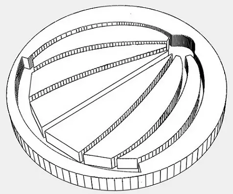
The figure below shows a wireframe 3D view of the hot and cold side heat exchangers.
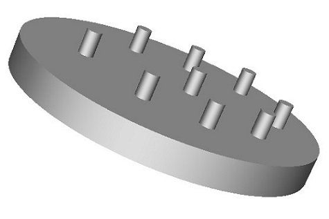
The figure below shows a 3D view of pin fins located on the other side of the hot and cold side heat exchanger (which is opposite the side the channels are on). The pin fins are in direct contact with the hot/cold fluid. The fins are arranged to get the maximum rate of heat transfer between the working gas and the hot/cold fluid, keeping in mind that the working gas is oscillating "back and forth" during engine operation, so it doesn’t only flow in one direction. Note that although pin fins are shown, other types of fins can be used, arranged in a manner to maximize the rate of heat transfer between the working gas and the hot/cold fluid.
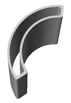
The figure below shows a picture of the regenerator housing.
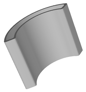
The figure below shows a second picture of the regenerator housing.
Pressure Vessel for the Engine
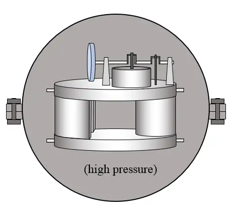
To minimize the stresses acting on the engine frame, the engine must be placed inside a pressure vessel that is pressurized to the mean engine pressure, as shown below. The engine is then connected to an alternator (not shown) to produce electricity. This is also placed inside the pressure vessel. Much of the wiring and tubing that is part of the engine system will have to come out of the pressure vessel (not shown). This allows for external control of the engine without having to open the pressure vessel in order to access the engine.
Crank Drive Design
The figures below show a basic schematic of the crank drive mechanism to be used in this engine, which has a gamma configuration. The phase angle difference between the two pistons is α, and the arrow shows the direction of rotation.
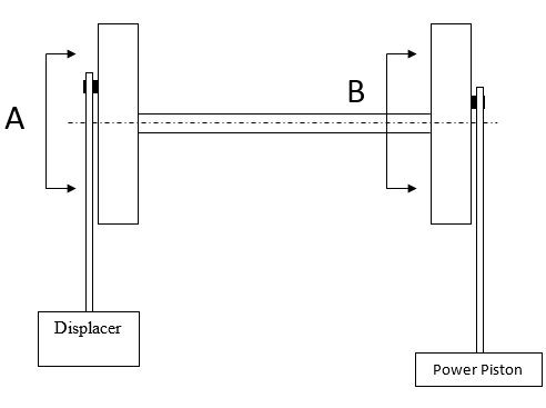
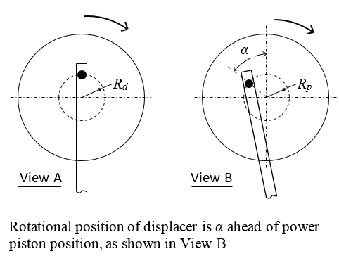
From the figures above, it is evident that the stroke length of the displacer = 2×Rd and the stroke length of the power piston = 2×Rp.
Gamma Configuration
The figure below shows a basic gamma configuration for a Stirling engine, which is the configuration used for this particular engine design.
Additional information
• This engine design is partly based on the information provided by the following PhD thesis on a 2.5 kW LTD Stirling engine: Stirling Engine for Solar Thermal Electric Generation, Mike Miao He, Electrical Engineering and Computer Sciences, University of California at Berkeley (http://www2.eecs.berkeley.edu/Pubs/TechRpts/2018/EECS-2018-15.pdf)
• In the first diagram, the tube joining the space between the power piston cylinder and displacer cylinder should be about 2-3 inches in diameter to minimize flow losses as the working gas shuttles back and forth between these two spaces. Similarly, hole 1 and hole 2 should also be 2-3 inches in diameter to minimize flow losses.
• Insulate around the hot end of the engine to reduce thermal losses to the environment.
• Perhaps use a regenerator matrix material made out of fiberglass, but keep it inside a fine mesh so the fibers don’t blow around the inside of the engine during operation.
• The ideal porosity of the fiberglass is about 86%, which can be achieved by compressing it to 30% of its original (uncompressed) volume (based on Berkeley thesis description on page 32).
• The two separate plates making up the heat exchanger assembly must be joined together with enough bolts to prevent "separation" when the engine is pressurized. A separation would seriously compromise heat transfer and hurt engine performance.
• Use aluminum components for the engine housing, where possible, and steel for the crankshaft and linkage components for maximum strength.
• The alternator connected to the engine will function as a generator to produce electricity, and as a starter to start the engine.
• At the topmost and bottommost position of the displacer, it should almost touch the top and bottom (respectively) of its cylindrical housing. This is to minimize dead volume in the engine.
• At the bottommost position of the power piston, it should almost touch the bottom of its cylindrical housing. This is to minimize dead volume in the engine.
• To keep the engine well sealed around junction points, to minimize gas leakage and pressure loss, use high temperature silicone (RTV silicone) which is cheap to buy and can withstand a maximum continuous temperature of 316 degrees Celsius.
• The pressure vessel for the engine must be able to withstand high internal pressure which is to be equal to the mean engine pressure. The engine is pressurized separately from the pressure vessel.
• The engine must be dynamically balanced.
• The optimal fin arrangement for optimal heat transfer must be determined using suitable software.
• Use Nitrogen as the working gas inside the engine.
• Special attention must be given to the bearing selection used in the moving parts of the engine, such as the linkages that move the power piston and displacer. The power piston and displacer must move up and down with ease with minimal lateral movement and lateral forces.
• Components must be sized appropriately to withstand forces during engine operation. Note that the forces acting on the power piston linkage are large, while the forces acting on the displacer linkage are relatively small.
• The pressure inside the engine is fairly uniform during operation.
• Use filled PTFE (Teflon) seals between the power piston and cylinder wall and between the displacer and cylinder wall, in order to prevent gas leakage.
• The hot and cold fluid need a high flow rate through the heat exchanger to maintain a roughly constant hot/cold temperature at the heat exchanger surface. This improves the thermal efficiency of the engine.
• The optimal heat exchanger is one that maximizes the rate of heat transfer between the hot/cold fluid and the working gas. This needs to be accomplished by maximizing the overall heat transfer coefficient in the heat exchangers, while also minimizing the difference in temperature between the hot/cold fluid and the working gas (which is flowing through the flow channels).
• Since the engine will be placed in a pressure vessel, the engine lubrication (such as used in the linkages) will be exposed to high pressure. Care must be taken that the lubrication is safe in this high pressure environment.
• Do not use oil-based lubrication in the contact area between the power piston and cylinder wall, nor between the displacer and cylinder wall. Any lubrication used here must be "dry", such as with PTFE seals. Any oil-based lubrication can evaporate under the high-pressure and high-temperature conditions and foul the heat exchangers, which will then be much less effective.
• Other design issues, not mentioned, will surely arise.
Note that the information given here is a starting point and does not encompass the whole design. Below are listed the things that also need to be done, that aren't discussed here, and which will depend on the particulars of your engine design; particulars such as power requirement and available hot source temperature.
• Heat transfer analysis to determine the optimal heat exchanger design
• Strength analysis to determine the required size of the engine components to satisfy strength requirements. Keep in mind that the weight of the components need to be as low as possible.
• Calculate the power piston diameter and stroke length
• Calculate the displacer diameter and stroke length
• Calculate the regenerator void volume
• Calculate the number of flow channels in the heater and cooler, and their dimensions
• Additional design issues as they come up
As I mentioned, the information presented here does not encompass the whole design, but it does help you to move towards an optimized design faster than you would otherwise.
Below are two files you can download which give a basic design outline for a low temperature Stirling engine, rated at 2 kW maximum power. I came up with this design after extensive reading, and then applying my Stirling engine software program.
2 kW low temperature Stirling engine design
2 kW low temperature Stirling engine design - simulation results
The above ".txt" file is created by the Stirling engine software program. This file can be opened with Notepad (in Windows). Make sure "Word Wrap" (in the Format menu) is not selected, otherwise some of the data won't display properly.
This ".txt" file contains the program input at the very top. This way, you know the input corresponding to the results. Engine performance data, such as speed and power, is given at the very bottom of this file.
Return to Engineering page
Return to Real World Physics Problems home page
Free Newsletter
Subscribe to my free newsletter below. In it I explore physics ideas that seem like science fiction but could become reality in the distant future. I develop these ideas with the help of AI. I will send it out a few times a month.