Instant Center
For rigid bodies experiencing general plane motion (in two-dimensions), the concept of instant center allows one to conveniently calculate the unknown angular velocity of the rigid body, or unknown linear velocities of points on the rigid body. The instant center is an imaginary point that allows for a mathematical “shortcut” in calculating these unknowns.
The instant center is also called the instantaneous center of zero velocity (IC). It lies on an imaginary axis of zero velocity, about which the body appears to rotate at a given instant. This axis is always perpendicular to the plane of motion.
There are three basic cases to consider when solving problems using the instant center approach.
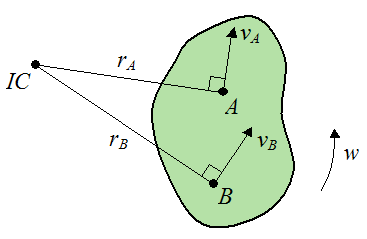
Case 1 – Consider a rigid body rotating in a plane. We wish to determine the velocity of a point A on the rigid body given the known velocity of another point B on the rigid body. The directions of the velocities are known and they are nonparallel. The figure below illustrates the set up of the problem.
Where:
vA is the velocity of point A, at the instant shown
vB is the velocity of point B, at the instant shown
IC is the intersection of the lines rA and rB
rA is the distance from the IC to point A, at the instant shown. This distance is drawn as perpendicular to the velocity vA
rB is the distance from the IC to point B, at the instant shown. This distance is drawn as perpendicular to the velocity vB
w is the angular velocity of the rigid body, at the instant shown
The distances rA and rB are generally determined from the geometry of the rigid body, and trigonometry.
Note that the lines rA and rB are drawn in the direction that will result in them converging to a point (the instant center IC).
Also note that the direction of the velocities vA and vB correspond to the direction of rotation of the rigid body.
The velocity of point A is given by
The velocity of point B is given by
Combine equations (1) and (2) to eliminate the variable w, and we get

Equations (1), (2), and (3) can be used to solve for any two unknowns in the equations, with the remaining variables known.
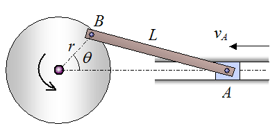
Example Problem for Case 1
Find the velocity of point B in the crank mechanism if the velocity of point A is vA, in the direction shown. The information is given in the figure.
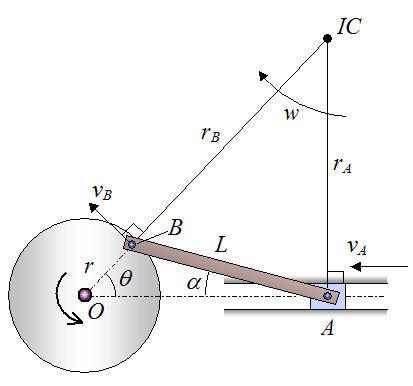
Solution
Set up the solution as drawn below, with new variables introduced as shown. The line rA is drawn as perpendicular to velocity vA. The line rB is drawn as an extension of the line passing through point O and point B.
Point B traces a circle during the motion of the crankshaft. By geometry, the velocity vB is tangent to this circle at point B. Also by geometry, the line rB is perpendicular to the velocity vB.
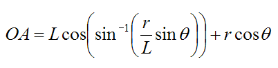
By geometry, the distance OA is given by

Also,
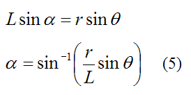
Substitute equation (5) into equation (4) and we get
The points O, A, and IC form a right-angled triangle. Therefore we can use trigonometry to solve for rA and rB:
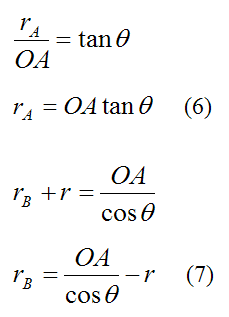
With vA known, substitute equations (6) and (7) into equation (3), to solve for the velocity of point B (VB).
Therefore,
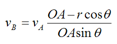
Note that when θ = 0, VB = ∞. This is because rA = 0 and as a result equation (3) can no longer be used. The angle θ = 0 is an example of a degenerate case where the instant center approach cannot be used to solve the problem.
For Case 1, a special case exists where the velocities at points A and B are pointing in the same direction (parallel), and the line passing through points A and B is not perpendicular to the direction of these velocities. For this case, the lines rA and rB are parallel and do not intersect. This means that rA and rB are infinitely long, and the IC lies at infinity. As a result, w = 0 and all the particles in the rigid body have the same velocity (i.e. the magnitude of the velocities and the direction of the velocities of all the particles in the rigid body are the same).
Case 2 – Consider a rigid body rotating in a plane. We wish to determine the angular velocity of the rigid body given the known velocities of points A and B on the rigid body. These velocities are parallel and pointing in the same direction. The line joining points A and B is perpendicular to the direction of the velocities. The figure below illustrates the set up of the problem.
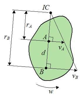
Note that IC is the intersection of the line passing through points A and B, and the line joining the tip of the vectors vA and vB.
The distance between points A and B is d.
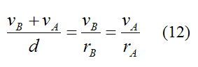
By similar triangles:
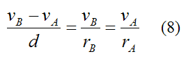
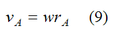
The velocity of point A is given by
The velocity of point B is given by
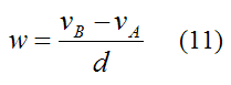
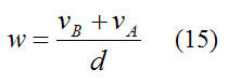
Combining equations (8)-(10), it follows that the angular velocity is
Example Problem for Case 2
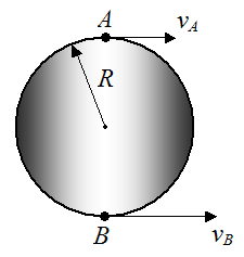
A wheel of radius R has velocities as shown at points A and B. Determine the angular velocity of the wheel.
Solution
The distance between points A and B is 2R. From equation (11) the angular velocity is
Case 3 – Consider a rigid body rotating in a plane. We wish to determine the angular velocity of the rigid body given the known velocities of points A and B on the rigid body. These velocities are pointing in parallel, but opposite directions. The line joining points A and B is perpendicular to the direction of the velocities. The figure below illustrates the set up of the problem.
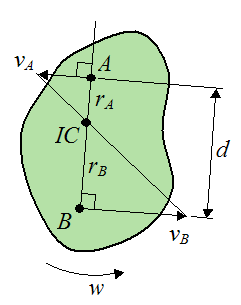
Note that IC is the intersection of the line passing through points A and B, and the line joining the tip of the vectors vA and vB. Unlike the previous case, the IC lies in between points A and B.
The distance between points A and B is d.
By similar triangles:
The velocity of point A is given by
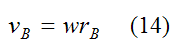
The velocity of point B is given by
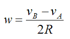
Combining equations (12)-(14), it follows that the angular velocity is
Example Problem for Case 3
A wheel of radius R has velocities as shown at points A and B. Determine the angular velocity of the wheel.
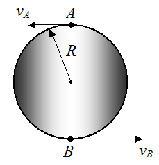
Solution
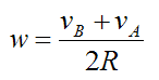
The distance between points A and B is 2R. From equation (15) the angular velocity is
In Closing
Note that the spatial location of the instant center can change with time. So in general its use only applies at the instant considered, which corresponds to the information given in the problem, at the instant considered. In general, if the velocities of points A and B change, and/or their directions change, a new instant center must be calculated to solve for the (new) unknown linear velocities, or angular velocities.
In general, the instant center approach should not be used for finding the acceleration of points in a rigid body. This is because the instant center (IC) does not generally have zero acceleration.
Return to Kinematics page
Return to Real World Physics Problems home page
Free Newsletter
Subscribe to my free newsletter below. In it I explore physics ideas that seem like science fiction but could become reality in the distant future. I develop these ideas with the help of AI. I will send it out a few times a month.