Bicycle Physics
Bicycle physics is a broad and complex subject, perhaps more so than one can imagine. Although the number of components of a bicycle is small, the interaction between them and the dynamic principles involved, is complicated. This is especially true with regards to bicycle stability, which is the result of a complex dynamic interaction within the bike-rider system.
On this page I will explain some of the main aspects of the physics of bicycles, which should give the reader a greater appreciation of how bicycles work, from a physics perspective.
Bicycle Physics – Stability
Bicycles are inherently stable when riding. Even riderless bicycles are stable if given enough forward velocity. Much effort has gone into analyzing the factors which make a bicycle stable. It has been determined that "trail" (shown below) is often an important contributor to bicycle stability. For the traditional bicycle design, if trail is positive, meaning the projection of the steering axis with the ground is in front of the contact point of front wheel and ground, then the bicycle is more stable when riding (i.e. it's less likely to fall over when riding it). If this projection is behind the contact point (negative trail) then the bicycle is less stable and the bicycle is more likely to fall down when riding it.
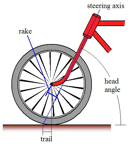
Based on the geometric parameters shown, the mathematical formula for trail is:
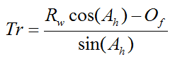
where Rw is the wheel radius, Ah is the head angle as shown, and Of is the rake, as shown, also known as the fork offset.
When analyzing bicycle stability it is common to use two parameters; the lean angle and steering angle of the bike. The lean angle is the left and right angle the bike frame makes with a vertical plane, and the steering angle is the angle the front wheel makes with the plane of the bike (containing the bike frame). The figure below illustrates the lean and steering angle.
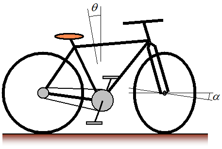
where θ is the lean angle and α is the steering angle. The sign convention for these angles is typically as follows, and is with respect to a rider sitting on the bike: Right lean is positive θ and left lean is negative θ. Right steer is positive α and left steer is negative α. For stability analysis both of these angles are the only independent variables needed to mathematically analyze bicycle stability. They completely describe the orientation of a bicycle as it travels in the forward direction. For a bicycle to be stable the lean and steering angle must have a tendency to "die out", which means that these angles will fluctuate around zero with small positive and negative values. This in turn means that the bicycle tends to stay upright with little turning, while moving in the forward direction. It is interesting that locking the front steering will always result in a bicycle falling over. The physics of stability requires that the front wheel can freely steer.
As mentioned, analyzing bicycle stability is a complex undertaking involving large and "messy" equations. There are too many physical interactions taking place between the various bicycle components (namely the front and back wheel, steering column, and bicycle frame) to allow for a completely intuitive explanation. To gain an appreciable understanding of bicycle stability it is best to do a full dynamics analysis and then base your understanding on the results of this analysis.
It is common to analyze bicycle stability using a "riderless" assumption. This means that the bicycle is modeled with just the bike by itself (with no rider). This greatly simplifies the analysis, and consequently it is often assumed that a stable riderless bicycle will also be stable with a rider present. This can be a reasonable assumption but unfortunately it ignores the "input" of the rider which also affects how stable a bike is during its use.
Nevertheless, in the absence of something better it is common to perform stability analyses on riderless bicycles. If you want to see the full analysis of a riderless bicycle see the following paper:
Linearized dynamics equations for the balance and steer of a bicycle: a benchmark and review, J. P. Meijaard, Jim M. Papadopoulos, Andy Ruina, A. L. Schwab, June 2007.
Gyroscopic Effects On Bicycle Stability
A common belief is that gyroscopic effects by themselves are what makes a bike stable. This is actually not the case. Although gyroscopic effects do play a role, they are merely part of a much larger dynamic interaction taking place between the various bicycle components, which altogether is what ultimately makes a bicycle stable during riding. The design of a bicycle, and the configuration of the different components, have been optimized through the ages (largely through trial and error), to make it as stable as possible.
As mentioned, gyroscopic effects are not the main contribution to bicycle stability, but it is still informative to see how gyroscopic effects contribute to stability. To understand this contribution consider the following scenario:
Let's say a riderless bicycle is moving at a certain velocity. Let's further say that the bicycle leans right (positive θ). This causes the front wheel to steer right (positive α) due to a gyroscopic effect. To help you understand why this happens, think of what it would take to prevent the front wheel from steering right. You would have to apply a torque in the left (opposite) direction, on the handlebars, to prevent the front wheel from steering right. Therefore, with torque absent (on a riderless bike) the front wheel naturally steers right. You can try this out yourself on a bike. Lift a bike off the ground and quickly spin the front wheel in the forward direction. Then, slightly tilt the bike frame left or right, and watch what happens to the front wheel in response. Compare this to what happens when you don't spin the front wheel, when tilting the bike.
With the front wheel steering right, the bicycle then travels in a circular path (towards the right). This decreases θ due to the effect of centripetal acceleration. This in turn causes the bicycle to lean left (negative θ) which causes the front wheel to steer left (negative α), which then causes the bike to travel in a circular path (towards the left), once more due to the effect of centripetal acceleration. This decreases θ (bicycle leans right) which again causes the front wheel to steer right, and on and on. The same chain of events happens if the bicycle initially leans left (negative θ). This chain of events keeps the bicycle from falling over.
The entire physical interactions taking place are actually more complex than the scenario given above, especially due to oscillations in θ and α. But the simplified scenario given above serves to highlight the contribution that gyroscopic effects make in keeping a bicycle stable.
Leaning Into A Turn
Source: http://en.wikipedia.org/wiki/Bicycle_and_motorcycle_dynamics. Author: http://en.wikipedia.org/wiki/User:Furmanj
When riding a bicycle it is necessary to lean into a turn in order to compensate for the effect of centripetal acceleration. The inward lean balances the centripetal acceleration which makes the turn possible without falling over.
To analyze the physics behind a lean consider the following schematic.
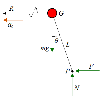
Where:
θ is the lean angle
R is the radius of the turn measured from the center of mass G of the bike-rider system
ac is the centripetal acceleration of the center of mass G of the bike-rider system
m is the mass of the bike-rider system
g is the acceleration due to gravity, on earth, which is 9.8 m/s2
L is the distance from point G to the effective contact point P between bicycle and ground
N is the normal force between bicycle and ground
F is the friction force between bicycle and ground, in the direction of ac
Since there is no acceleration in the vertical direction the sum of the vertical forces is zero. Thus,
Apply Newton's second law in the horizontal direction:
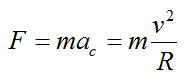
where v is the velocity of the bicycle around the turn.
Sum the moments about point G:
(Note that we are ignoring three-dimensional effects in this equation. They are assumed to be negligible).
Combine the above three equations to find an expression for the angle of lean θ. We have
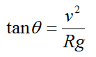
In the next section we will look at forces and power.
Forces and Power
The figure below shows a bicycle going uphill at an angle of inclination Φ, and with a velocity V.
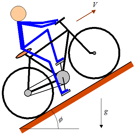
To propel the bicycle uphill the rider must push down on the pedals. The pedals are offset 180° which means that only one pedal can be pushed at a time, from the top position to the bottom position, and then switching to the other pedal.
Given a force F1 acting on the pedal we can calculate the resulting force F4 between the rear wheel and ground. This is the force that propels the bicycle forward.
We can perform a torque analysis with good accuracy based on the assumption that acceleration (linear and angular) is negligible. Hence, we can treat this as a static problem.
Consider the figure below, with forces and radial dimensions shown.
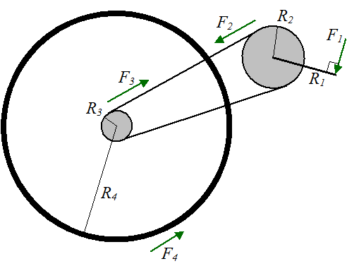
Where:
F1 is the force applied to the pedal
R1 is the pedal radius
F2 is the force acting on the main crank, due to chain contact
R2 is the main crank radius
F3 is the force acting on the rear gear, due to chain contact
R3 is the rear gear radius
F4 is the force acting on the rear wheel, due to contact with the ground. Note that the coefficient of static friction between wheel and ground must be large enough to support this force, otherwise slipping occurs
R4 is the rear wheel radius
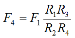
Using the static equilibrium assumption, we can write the following torque equations:
and
Since F2 = F3, we can combine the above two equations to give an expression for F4:
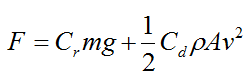
The force F4 is what propels the bicycle forward. If we assume that the bicycle is moving at constant velocity (no acceleration) then the force F4 must equal the resisting forces opposing the bicycle's motion. These resisting forces are gravity, rolling resistance, air drag, and internal bicycle friction. If we neglect the latter we can then write the following mathematical expression:
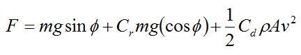
Where:
F is the force propelling the bicycle forward. Note that F ≡ F4
Cr is the coefficient of rolling resistance, which can be 0.0022 to 0.005 for bicycle tires (ref: http://en.wikipedia.org/wiki/Rolling_resistance)
Cd is the drag coefficient
ρ is the density of the air through which the bicycle is moving
A is the projected cross-sectional area of the bike+rider perpendicular to the flow direction (that is, perpendicular to v), and v is the speed of the bicycle relative to the air
The first term on the right side of the above equation is the gravity contribution. The second term is the rolling resistance contribution. The third term is the air drag contribution.
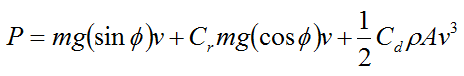
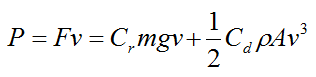
To evaluate the power P required to propel the bicycle, multiply the above equation by v. We get P = Fv, and
For a flat surface (no incline) set Φ = 0. We get
and
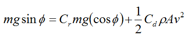
We can also solve for the terminal velocity of a bicycle coasting down a hill with given inclination angle of Φ. Since the rider in this case does not exert any force on the pedals, we have F ≡ F4 = 0. Hence, the force of gravity must balance the resistive forces due to rolling resistance and air drag. Hence, we can solve for the terminal coasting velocity v in the following equation:
Naturally, when riding a bike we wish to keep resistive forces opposing motion as low as possible. This is accomplished by keeping the tires well pressurized (which minimizes rolling resistance) and keeping the frontal area A as small as possible to reduce air drag, especially when traveling at high speeds, such as in a race. Typically, the rolling resistance is much higher than air drag so reducing A is not important for the average rider who travels at moderate speeds.
A Fun Experiment
Try out this fun experiment related to bicycle physics (shown below). Stand a bicycle upright and orient one of the pedals so that it's at the bottom position. Next, push left on the pedal. Which way does the bicycle move?
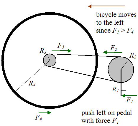
Answer: The bicycle moves to the left (which might be non-intuitive to you). Even though the force you are applying to the pedal turns the main crank clockwise, which is the direction required to move the bike to the right, the bicycle ends up moving left. This is because the external force F1 you are applying to the bike, results in a lesser force F4 in the opposite direction. Since F1 > F4, the bicycle moves left. Now, if you were to sit on the bike and apply a force F1 with your foot, the bicycle would move to the right since F1 is now an internal force in the bike-rider system and hence the only external force acting on the bicycle is F4 acting on the rear wheel, which pushes the bicycle to the right.
Return to Miscellaneous Physics page
Return to Real World Physics Problems home page
Free Newsletter
Subscribe to my free newsletter below. In it I explore physics ideas that seem like science fiction but could become reality in the distant future. I develop these ideas with the help of AI. I will send it out a few times a month.