Water Rocket Physics
Water rockets are fun toys for people of all ages, even adults. They work based on a simple physics concept in which water is forced out the bottom of the rocket by air pressure, and in doing so exerts an upward force pushing up on the rocket (Newton's third law). This upward force causes the rocket to shoot upward at high speed. The way a water rocket works is by filling it up partially with water and then pressurizing the inside with air. When the bottom nozzle is opened the internal air pressure forces the water out of this nozzle at high speed causing the rocket to shoot straight up at high speed.Water rocket enthusiasts have created all sorts of amazing water rocket designs, including this one shown in the video below which is a two-stage water rocket.
Next I will get into some of the physics of water rockets. The analysis will be somewhat advanced, but it's a means to an end in which the end result will help you build and set up a water rocket that will reach a maximum height in the air.
Water Rocket Physics Analysis
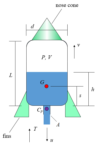
The figure below shows a schematic for this analysis.
Where:
d is the diameter of the rocket body
L is the length of the rocket body
P is the air pressure inside the rocket body
V is the air volume inside the rocket body
G is the center of mass of the rocket + water system (where the water is that which is contained inside the rocket body). Note that the mass of the air inside of the rocket is small enough to be ignored
Cp is the center of pressure (of the air drag force) for the rocket when it is in flight
A is the cross-sectional area of the rocket nozzle (through which the water exits)
u is the velocity of the exiting water relative to the rocket
T is the thrust exerted on the rocket, created by the exiting water
s is the distance from the bottom of the rocket body to the center of mass G
h is the height of the water, as shown
v is the velocity of the rocket, with respect to ground
The nose cone (shown in the above figure) reduces air resistance as the rocket flies through the air. Also note that we are assuming a thin-walled rocket body in which the dimensions d, L, h, and s are approximately the same (with negligible difference) whether measured from the interior surfaces of the rocket body or from the exterior surfaces of the rocket body.
When the rocket nozzle is opened the water starts to exit at high speed due to the pressure inside the rocket body forcing the water out. As the water exits it accelerates downward due to a large downward force (caused by the internal pressure). By Newton's third law there is also an equal and opposite force pushing upward on the rocket, causing it to accelerate upward. As the water exits, the water height h drops. This causes the center of mass G to drop to a lower level relative to the rocket body, resulting in a lower distance s. As the water continues to exit the distance s eventually reaches a minimum value and then begins to rise again until no water is left inside the rocket body, and the distance s will correspond to the distance to the center of mass of just the rocket body.
As the rocket speed increases it encounters air resistance (drag) which can cause the rocket to tumble end over end. To prevent this fins must be placed on the rocket (shown in the above figure) which cause the resultant drag force from air resistance to act at a point underneath G, known as the center of pressure Cp. This will enable the drag force to keep the rocket aligned with its flight path, and tumbling will not occur. The fins must be located low enough on the rocket body so that the center of pressure Cp is always below G (the position of which changes as the water exits). This will guarantee that the rocket will never tumble at any time during its flight, and it will therefore be stable as it flies through the air. The trade off of placing fins is that they are a source of air resistance and cause additional drag force on the rocket as a result, but without them the rocket would tumble as it flies through the air and not go very high as a result.
We will now develop the equations to model the flight of a water rocket.
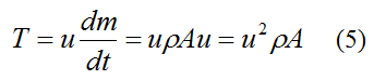
The thrust T for a water rocket is the same as for chemical rockets described in the rocket physics page. The thrust is given by:
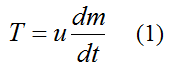
where m is the mass of the water rocket (rocket body + water), and t is time.
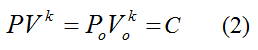
We can reasonably assume that, when the water is exiting, the volume of air inside the rocket body expands quickly enough so that it has no time to experience either heat gain from the external environment or heat loss to the external environment. In thermodynamics this is called an adiabatic expansion (or an isentropic process), and it can be represented mathematically by the following equation:
Where:
C is a constant
k is a thermodynamic constant, which for air is equal to 1.4
Po is the initial absolute pressure of the air inside the rocket body, before the water is released
Vo is the initial volume of the air inside the rocket body, before the water is released
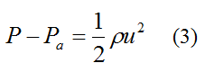
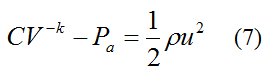
From Bernoulli's equation for constant density fluid flow,
Where:
Pa is the air pressure outside the rocket body. This is assumed to be constant over the flight distance of the rocket
ρ is the density of water, which is 1000 kg/m3
Note that P − Pa is the gauge pressure that an air pump reads when pressurizing.
This equation assumes the following:
• The flow velocity of the water at the air-water interface inside the rocket body is negligible compared to the outlet flow velocity u. Note that the flow velocity is the velocity relative to the rocket.
• The gravitational change in energy of the water as it changes elevation while flowing from inside the rocket body to outside has negligible contribution.
• Quasi-steady flow conditions for the water, with negligible fluid friction.
Now,
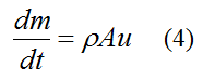
From equation (1)
Substitute this equation into equation (3) and we get
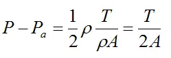
Solve for T and we get
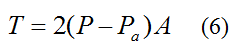
Substitute equation (2) into equation (3). This gives us
We now seek an equation in which u can be calculated as a function of time. This will then allow thrust T to be given as a function of time. Differentiate equation (7) with respect to time. This gives us
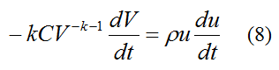
where dV/dt is the rate of change of air volume inside the rocket body. This is equal to the volume flow rate of water exiting the rocket body. Therefore,
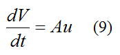
Substitute this equation into equation (8). We get
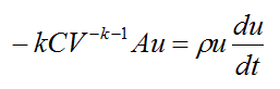
Substitute for V from equation (7) into the above equation and simplify. This gives us
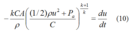
u can only be solved for using numerical integration, using the initial condition u = uo at time t = 0. Note that uo can be solved for from equation (3) given an initial gauge pressure P − Pa (as measured by an air pump).
From equation (5),
We can substitute for u calculated from equation (10) into this equation to give T as a function of time.
An interesting and practical problem is to determine the maximum height reached by a water rocket, taking into account air resistance. By Newton's second law the (one-dimensional) force balance for the water rocket is
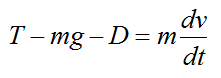
where g is the acceleration due to gravity (9.8 m/s2) and D is the drag force due to air resistance. This is given by
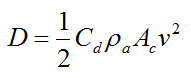
Where:
Cd is the drag coefficient
ρa is the density of air
Ac is the cross-sectional area of the rocket body in the direction of v
Therefore the force balance for the water rocket becomes
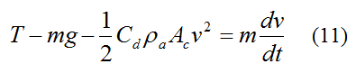
Substitute equation (5) into equation (11) and we can solve for v and therefore the peak height reached using numerical integration. Since the mass m (mass of rocket body plus water) changes with time we need to use equation (4) in conjunction with the above equation. In using the above equation we shall assume that the water velocity inside the rocket body, relative to the rocket body (as h decreases), is negligible compared to the upward velocity v of the rocket body.
Equation (11) is only valid up until the point the peak height is reached. This is because (in this equation) the drag term does not reverse sign to oppose motion when the rocket velocity v changes sign (and becomes negative) when the rocket falls after the peak height is reached. To deal with the rocket velocity changing sign after the peak height is reached we simply make the drag term positive (instead of negative) after the peak height is reached, and this will properly account for drag. However, we do not need to do this because we are only interested in properly modeling the flight of the rocket up to the point the peak height is reached, which enables us to accurately predict the peak height reached, which is all we care about.
A nice optimization problem is to determine how much water to put in the rocket body to obtain the maximum height, given an initial pressure.
The equations derived here have been incorporated into an Excel spreadsheet which you can easily use to help you design a water rocket that reaches the maximum height possible. To download the Excel spreadsheet right-click on this link. This Excel file is in compressed "zip" format and you have to uncompress it before you can use it.
Additional Information
Filling the rocket with pressurized air only will not result in nearly as great a height reached as you would by filling the rocket with pressurized air and water. This is because the escaping air in the air-only rocket (upon being released) obtains a greater share of the stored energy (from the initial pressurization) than escaping water would in a water rocket. This is due to the much greater mass of water than air, inside the rocket. This process is analogous to firing a bullet from a gun. The bullet, having much less mass than the gun, obtains a much greater share of the gunpowder energy than the gun. If you want the gun to have a greater share of the energy (and hence a greater recoil speed after firing), then the bullet must have more mass. By analogy, the bullet represents the contents of the rocket (either air only or water + air), and the gun represents the rocket body. Since water has a much greater mass than air (inside the rocket), the result is that the rocket body will obtain a much greater share of the stored energy. This translates into much greater kinetic energy of the rocket (and therefore much greater speed) than an air-only rocket, which will result in it reaching a much greater height than an air-only rocket. To see a detailed proof of this concept see Difference Between Momentum And Kinetic Energy.
Ideally the rocket is pressurized so that, as the last of the water exits, the pressure inside the rocket is at atmospheric pressure. This represents the most efficient design, even though it won't necessarily result in the greatest height reached for a given initial pressure. If the air pressure inside the rocket is greater than atmospheric pressure, as the last of the water exits, then the air will of course shoot out the bottom and some additional thrust (and speed) will be given to the rocket. However, this is not accounted for here given that its contribution to peak height reached is almost negligible, for reasons given in the previous paragraph.
Completely filling the water rocket with water will prevent it from being pressurized since water is incompressible for the typical pressures used in water rockets.
If the mass of the rocket body (water excluded) is too small, the drag force will be excessively high relative to the gravity force, during the part of the flight stage where there is no thrust. As a result, the height reached by the rocket will actually be less than for a heavier rocket body. As an analogy, if you launch a Styrofoam ball and a metal ball of the same size straight up into the air, both with the same initial kinetic energy, the metal ball will reach a greater height even though the Styrofoam ball has to be launched with much greater speed in order to have the same kinetic energy as the metal ball (due to its much lower mass).
The typical water thrust stage for a bottle size rocket is very short, typically lasting a tenth of a second or so. This is how long it takes for all the water to exit the rocket. During this time period the rocket accelerates very quickly.
A long and narrow rocket body (long L and small d) may be better since it can withstand greater pressure without bursting, and it also has a lower Ac which reduces drag from air resistance.
Return to Miscellaneous Physics page
Return to Real World Physics Problems home page
Free Newsletter
Subscribe to my free newsletter below. In it I explore physics ideas that seem like science fiction but could become reality in the distant future. I develop these ideas with the help of AI. I will send it out a few times a month.