About me and why I created this physics website.
Amusement Park Physics
Understanding amusement park physics is a great way to give you an appreciation of the dynamics of the various rides.What makes amusement park rides so much fun is the forces your body experiences when you're on them. There are turns, twists, and rapid acceleration. It's quite different from what we experience on a daily basis. But it is precisely these unusual sensations of having your body pushed and pulled in different directions, that keeps people coming back for more.
However, designing these rides is much more than just putting in random loops on a track. A solid understanding of the physics is necessary for the designers in order to push the safety limits for humans as much as possible. So having an idea of how much force the body will experience on a ride is a key factor when deciding how fast, how high, or how big a radius is required.
Click on the links below to learn about the physics involved in these particular rides.
Ferris Wheel Physics
Roller Coaster Physics
The Gravitron
Another popular amusement park ride is the Gravitron. In this ride people lean against the external wall and the force generated by centriptetal acceleration, during rotation, keeps the riders from sliding down the wall. The figure below shows a schematic of the ride.
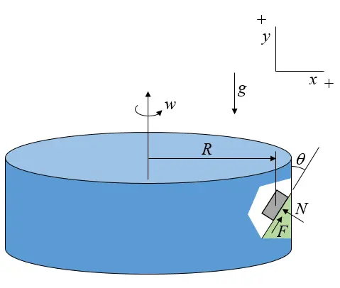
Where:
w is the angular velocity of the Gravitron
g is the acceleration due to gravity (9.8 m/s2)
R is the radius of rotation measured from the center of rotation of the Gravitron to the center of mass of the rider (represented by the gray rectangle).
θ is the angle of lean which the external wall of the Gravitron makes with the vertical
F is the friction force between the rider's body and the external wall of the Gravitron
N is the normal force between the rider's body and the external wall of the Gravitron
The coordinate system of the ride is given as shown and it is assumed that the ride is horizontal.
We wish to determine the minimum rotational speed (w) of the Gravitron such that the rider does not slide down the external wall. In addition, we wish to determine the maximum rotational speed of the Gravitron such that the rider does not slide up the external wall. These values will depend on the angle θ and on the coefficient of static friction (μ) between the rider's body and the external wall of the Gravitron. Note that the coefficient of static friction used must be the minimum possible value. For example, let's say that the range for the coefficient of static friction (for different riders) is 0.25-0.40. We must use μ = 0.25. Using this value in the calculations (given below) results in a minimum and maximum value of w such that none of the riders slide down or up the wall, respectively. This is important for safety reasons.
Let us first determine the minimum rotational speed such that the rider does not slide down the external wall.
Apply Newton's second law to the rider, in the x-direction:
where m is the mass of the rider, and the term w2R is the centripetal acceleration of the center of mass of the rider, which points towards the center of rotation.
Apply Newton's second law to the rider, in the y-direction:
The limiting case for slipping occurs when the friction force F is equal to the maximum friction possible with no sliding occurring. For this limiting case,
Combine equations (1) - (3) and solve for w, which is then equal to the minimum rotational speed of the rider such that he/she does not slide down the external wall. We get,
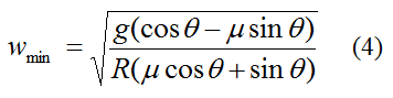
This equation is only valid for cosθ > μsinθ. If cosθ ≤ μsinθ the rider will never slide down the wall, even if the Gravitron is not spinning (where w = 0). Note that the units for wmin is radians/sec.
Next, let's determine the maximum rotational speed such that the rider does not slide up the external wall. For this case we solve the same equations as given above but the force F is given in the opposite direction shown in the above figure. In these equations we once more solve for w, which is then equal to the maximum rotational speed of the rider such that he/she does not slide up the external wall. We get,
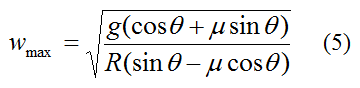
This equation is only valid for sinθ > μcosθ. If sinθ ≤ μcosθ the rider will never slide up the wall no matter how fast the Gravitron spins. For example, if θ = 0 the rider will never slide up the wall no matter how fast the Gravitron spins. Note, there is a ride called the Rotor which is a special case of the Gravitron, in which θ = 0. Note that the units for wmax is radians/sec.
Three Dimensional Amusement Park Rides
There are many other fun rides at amusement parks, dozens in fact, and many of them exhibit complex three-dimensional motion which is difficult to analyze from a physics perspective. Nevertheless I took it upon myself to create three Excel spreadsheets which can be used to analyze most of the three-dimensional rides found at amusement parks. The way to use these spreadsheets is to first match a ride to one of these spreadsheets, and then input the corresponding parameters of the ride into the spreadsheet. The spreadsheet will then calculate the maximum g-force experienced by a rider on the ride. The maximum g-force is an important value since it tells you what the maximum force experienced by a rider is on the ride. This can be very useful (and interesting) information when deciding which rides you want to avoid (or go on), depending on your personal preferences.
These three spreadsheets are categorized into three separate cases, which as mentioned, can be used to analyze most of the three-dimensional rides found at amusement parks. I describe these three cases below, and provide the corresponding spreadsheets to use when analyzing them.
Case 1
A general schematic of this ride is given in the figure below, with the xyz coordinate system as shown. This schematic shows a general representation for a large number of amusement park rides. These rides can be modeled by choosing the correct values for the parameters shown in the figure, and then entering these values in the spreadsheet and solving for the maximum g-force experienced by a rider on the particular ride.
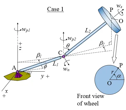
The parameters shown in this figure are defined as follows:
β1 is the rotation angle of the rod AC when projected on the xy plane, as measured from the positive y-axis
β2 is the rotation angle of the rod CO when projected on the xy plane, as measured from the projection of rod AC onto the xy plane
ϕ is the angle between rod AC and the xy plane. This angle is constant
θ is the angle between rod CO and the vertical (pointing in the z-direction)
α is the angular position of OP, as shown
The angular velocity vector wp1 = dβ1/dt. This is generated by a rotating motor located at point A, which is attached to ground.
The angular velocity vector wp2 = dβ2/dt. This is generated by a rotating motor located at point C, which is attached to arm AC.
The angular velocity vector ws = dα/dt. This is the wheel spin rate, which is generated by a rotating motor located at point O and attached to arm CO.
The angular velocity vector wn = -dθ/dt. This is not an important quantity to understand, but is given because it helps to visualize the kinematics. This is generated by a rotating motor located at point C and attached to arm AC.
L1 is the length of rod AC
L2 is the length of rod CO
r is the radius of the wheel (which is the distance OP)
Note that the angular velocity vector wn is always parallel to the xy plane. Also, the angular velocity vectors wp1 and wp2 are always parallel to the vertical z-axis.
The rider is located at point P.
Case 2
A general schematic of this ride is given in the figure below, with the xyz coordinate system as shown. This schematic shows a general representation for a large number of amusement park rides. These rides can be modeled by choosing the correct values for the parameters shown in the figure, and then entering these values in the spreadsheet and solving for the maximum g-force experienced by a rider on the particular ride.
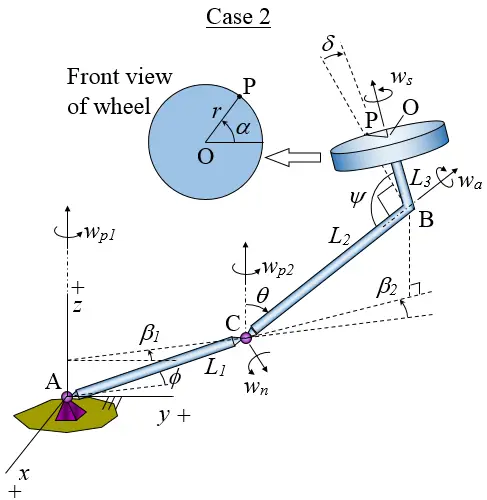
The parameters shown in this figure are defined as follows:
β1 is the rotation angle of the rod AC when projected on the xy plane, as measured from the positive y-axis
β2 is the rotation angle of the rod CB when projected on the xy plane, as measured from the projection of rod AC onto the xy plane
ψ is the angle between rod CB and rod BO. This angle is constant
ϕ is the angle between rod AC and the xy plane. This angle is constant
θ is the angle between rod CB and the vertical (pointing in the z-direction)
δ is the angular position of rod BO, as shown
α is the angular position of OP, as shown
The angular velocity vector wp1 = dβ1/dt. This is generated by a rotating motor located at point A, which is attached to ground.
The angular velocity vector wp2 = dβ2/dt. This is generated by a rotating motor located at point C, which is attached to arm AC.
The angular velocity vector wa = dδ/dt. This is the spin rate of elbow CBO about the axis CB. This is generated by a rotating motor located at point C, which is attached to arm AC.
The angular velocity vector ws = dα/dt. This is the wheel spin rate, which is generated by a rotating motor located at point O and attached to arm BO.
The angular velocity vector wn = -dθ/dt. This is not an important quantity to understand, but is given because it helps to visualize the kinematics. This is generated by a rotating motor located at point C and attached to arm AC.
L1 is the length of rod AC
L2 is the length of rod CB
L3 is the length of rod BO
r is the radius of the wheel (which is the distance OP)
Note that the angular velocity vector wn is always parallel to the xy plane. Also, the angular velocity vectors wp1 and wp2 are always parallel to the vertical z-axis.
The rider is located at point P.
Case 3
A general schematic of this ride is given in the figure below, with the xyz coordinate system as shown. This schematic shows a general representation for a large number of amusement park rides. These rides can be modeled by choosing the correct values for the parameters shown in the figure, and then entering these values in the spreadsheet and solving for the maximum g-force experienced by a rider on the particular ride.
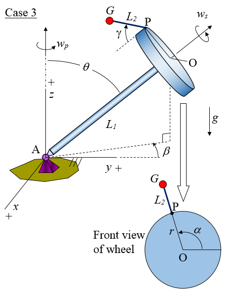
The parameters shown in this figure are defined as follows:
β is the rotation angle of the rod AO when projected on the xy plane, as measured from the positive y-axis
θ is the angle between rod AO and the vertical (pointing in the z-direction). This angle is constant
α is the angular position of OP, as shown
γ is the angle between PG and the side of the wheel, as shown
The angular velocity vector wp = dβ/dt. This is generated by a rotating motor located at point A, which is attached to ground.
The angular velocity vector ws = dα/dt. This is the wheel spin rate, which is generated by a rotating motor located at point O and attached to arm AO.
L1 is the length of rod AO
L2 is the length PG, as shown. This can be thought of as a rod connection between points P and G, in which the rod is constrained such that it can only swing in the radial direction
r is the radius of the wheel (which is the distance OP)
g is the acceleration due to gravity
Note that the angular velocity vector wp is always parallel to the vertical z-axis.
The rider is located at point G. When the ride is in motion the rider swings radially outward at an angle γ, which can change during the course of the ride (which depends on the type of ride).
The Excel spreadsheets used for analyzing all three cases can be downloaded here:
Case 1
Case 2
Case 3
The spreadsheets are in compressed "zip" format and you have to uncompress them before you can use them.
The following are example solutions for different amusement park rides. These are obtained using the spreadsheets for the three cases.
Zamperla Balloon Race
Case 3 can be used to analyze this ride.
From observation we have the following ride parameters (approximate):
Mass of G (for rider) = 70 kg (arbitrary, you can use any mass you wish)
Rope length L2 (PG) = 1.5 meters
Wheel radius r (OP) = 2.5 meters
θ = 0.5 radians (equal to 30 degrees)
Wheel spin rate ws = -1.6 radians/sec
Precession rate wp = 0.8 radians/sec
Arm length L1 (AO) = 1.4 meters
From the spreadsheet for Case 3, the calculated maximum g-force experienced by a rider at point G is approximately 1.4g (which is 1.4 times his/her body weight).
Note: We are assuming that the gondolas (containing the riders) can be modeled as a point mass (G). This is an approximation however, but it's reasonable and it simplifies the analysis.
Spin Out
Case 2 can be used to analyze this ride.
From observation we have the following ride parameters (approximate):
Precession rate wp1 = -0.8 radians/sec
Precession rate wp2 = 0 radians/sec
Wheel spin rate ws = -1.6 radians/sec
Elbow CBO spin rate wa = 0.5 radians/sec
Arm length L1 (AC) = 6 meters
Arm length L2 (CB) = 6 meters
Arm length L3 (BO) = 1 meter
Wheel radius r (OP) = 4 meters
θ = 1.2 radians (equal to 70 degrees)
dθ/dt = 0 (at all time)
ϕ = 3.14159 radians (equal to 180 degrees)
ψ = 1.57079 radians (equal to 90 degrees)
Gravity is pointing in direction 6 (the -z direction)
From the spreadsheet for Case 2, the calculated maximum g-force experienced by a rider at point P is approximately 2.8g (which is 2.8 times his/her body weight).
Enterprise
Case 3 can be used to analyze this ride.
From observation we have the following ride parameters (approximate):
Mass of G (for rider) = 70 kg (arbitrary, you can use any mass you wish)
Rope length L2 (PG) = 2 meters
Wheel radius r (OP) = 8 meters
θ = 1.4 radians (equal to 80 degrees)
Wheel spin rate ws = -1.6 radians/sec
Precession rate wp = 0 radians/sec
Arm length L1 (AO) = 0 meters
From the spreadsheet for Case 3, the calculated maximum g-force experienced by a rider at point G is approximately 3.6g (which is 3.6 times his/her body weight).
Orbiter Ride
Case 1 can be used to analyze this ride.
From observation we have the following ride parameters (approximate):
Precession rate wp1 = -1.6 radians/sec
Precession rate wp2 = 0 radians/sec
Wheel spin rate ws = -0.8 radians/sec
Arm length L1 (AC) = 4 meters
Arm length L2 (CO) = 2 meters
Wheel radius r (OP) = 2 meters
θ = 1.9 radians (equal to 110 degrees)
dθ/dt = 0 (at all time)
ϕ = 0.35 (equal to 20 degrees)
Gravity is pointing in direction 6 (the -z direction)
From the spreadsheet for Case 1, the calculated maximum g-force experienced by a rider at point P is approximately 2.1g (which is 2.1 times his/her body weight).
Star Flyer
Case 3 can be used to analyze this ride.
From observation we have the following ride parameters (approximate):
Mass of G (for rider) = 70 kg (arbitrary, you can use any mass you wish)
Rope length L2 (PG) = 10 meters
Wheel radius r (OP) = 10 meters
θ = 0 radians (equal to 0 degrees)
Wheel spin rate ws = 1.0 radians/sec
Precession rate wp = 0 radians/sec
Arm length L1 (AO) = 0 meters
From the spreadsheet for Case 3, the calculated maximum g-force experienced by a rider at point G is approximately 2.2g (which is 2.2 times his/her body weight).
Return to Real World Physics Problems home page