Trebuchet Physics
Source: http://en.wikipedia.org/wiki/Trebuchet
Trebuchet Physics – How A Trebuchet Works
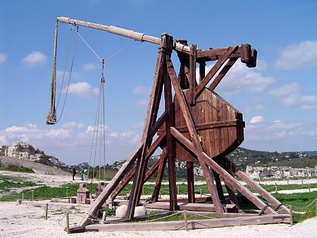
A trebuchet is a battle machine used in the middle ages to throw heavy payloads at enemies. The payload could be thrown a far distance and do considerable damage, either by smashing down walls or striking the enemy while inside their stronghold.
The trebuchet was preferred over a catapult due to its greater range capability and greater accuracy.
A trebuchet works by using the energy of a falling (and hinged) counterweight to launch a projectile (the payload), using mechanical advantage to achieve a high launch speed. For maximum launch speed the counterweight must be much heavier than the payload, since this means that it will "fall" quickly.
The motion of a trebuchet during launch can become fairly complicated, and cannot be fully understood using intuition alone. Therefore, one must analyze trebuchet physics in full in order to make accurate predictions.
In some designs a guide chute is used to guide the sling along and support the payload until the speed is great enough to hold it in the pouch alone. This will be discussed in more detail in the analysis section.
The beginning of the launch is illustrated in the figure below.
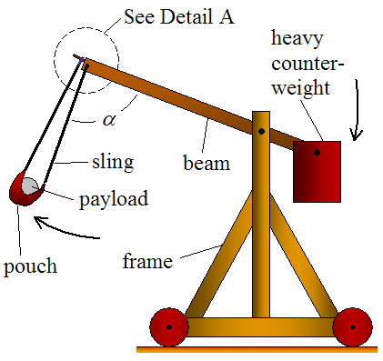
As you can see, the counterweight pivots around a much shorter distance than the payload end. The advantage of this is that the payload end of the beam reaches a much higher linear velocity than the counterweight end of the beam. This is the principle of mechanical advantage, and is what allows the payload to reach a high launch velocity. However, because the counterweight pivots around a much shorter distance, its weight must be much greater than the weight of the payload, to get a high launch velocity. However, increasing the mass of the counterweight beyond a certain point will not help, since the limiting speed of the falling counterweight is free-fall speed.
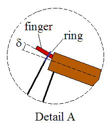
The sling releases when a certain angle α is reached. At this point the ring (which is connected to the sling and loops around the finger for support) slips off and the payload is launched. The release angle α can be adjusted by changing the finger angle δ. For a greater δ the release angle α increases. For a smaller δ the release angle α decreases.
The figure below illustrates the trebuchet at the release point.
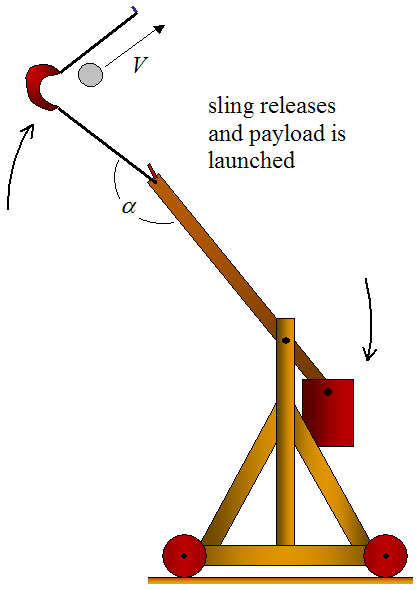
As the beam rotates clockwise (due to the falling counterweight), the payload experiences centripetal acceleration which causes it to move outwards (since it is unrestrained). This results in a large increase in linear velocity of the payload which far exceeds that of the end of the beam to which the sling is attached. This is the heart of trebuchet physics and is the reason a trebuchet has such great launching power.
However, it is worth noting that the physics of the trebuchet is not unique to the trebuchet. For example, in a golf swing the same basic physics applies. In fact, you can think of a trebuchet as an upside down golf swing. Thus, the physics of a trebuchet is very similar to the physics of a golf swing.
The optimal trebuchet design is one that launches the payload the farthest horizontal distance. This makes sense intuitively since range is a key factor when staging an attack on an enemy. The challenge then, is to find the optimal design to maximize the range. This is not a trivial task given that there are many variables one can adjust. Fortunately, such an optimization is greatly simplified given that trebuchet physics can be modeled with computers, saving a lot of time.
According to Donald B. Siano, in his analysis of trebuchet physics (Trebuchet Mechanics, March 28, 2001), the optimal release position and design, based on his definition of "range efficiency" is such that:
• The initial release position is such that the beam on the counterweight side makes an angle of 45° with the vertical.
• The length of the long arm of the beam (on the payload side) is 3.75 times the length of the short arm of the beam (on the counterweight side).
• The length of the sling is equal to the length of the long arm of the beam (on the payload side).
Furthermore, he recommends using a counterweight that has a mass 100 times greater than the mass of the payload. However, it is certainly possible to achieve a good design with a much lighter counterweight than this.
To aid designers and enthusiasts, I created a trebuchet simulator, programmed in Microsoft Excel. It's very useful for helping you come up with the winning design in a trebuchet competition! Click here to learn more about it.
Trebuchet Physics – Analysis
The development of the equations to fully analyze trebuchet physics is quite an onerous task, both to derive and fully present on a website. Therefore, the full mathematical development will not be presented here. Instead, the basic equations will be introduced in order to give the reader a basic understanding of the core physics and mathematics required to fully describe the physics of a trebuchet.
This will be modeled as a two-dimensional problem.
The following assumptions are made in this analysis:
• The trebuchet is rigid. There is no flexing of the various members.
• There is no friction on the guide chute (to be discussed), or at the joints (pivots).
• The pouch and sling have negligible mass.
• There is no air resistance as the payload flies through the air.
• The trebuchet remains stationary on the ground during launch.
Case 1 – Payload In Contact With Guide Chute
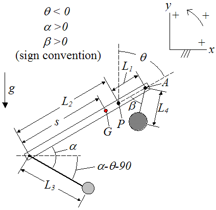
As mentioned before, some trebuchet designs use a guide chute to keep the payload in place during the initial part of the launch. This part of the launch is "constrained" since the payload can only move along the surface of the guide chute. This is illustrated with the following schematic. To simplify the analysis here, the sling is replaced with a single cable in tension attached to the payload and the end of the beam. The hinged counterweight is replaced with a mass suspended by a single cable attached to the other end of the beam. The guide chute is assumed to be frictionless.
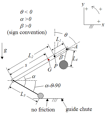
The variables are defined as follows:
L1 is the distance between the end of the beam (on the counterweight end, point A) and the fixed pivot about which the beam rotates (point P)
L2 is the distance between the end of the beam (on the payload end) and the fixed pivot about which the beam rotates (point P)
L3 is the length of the cable holding the payload
L4 is the length of the cable holding the counterweight
s is the distance between the end of the beam (on the payload end) and the center of mass of the beam (point G)
θ is the angle between the vertical and the beam, on the counterweight side, as shown. This angle is defined as negative
α is the angle between the beam and the cable holding the payload. This angle is defined as positive
β is the angle between the beam and the cable holding the counterweight. This angle is defined as positive
g is the acceleration due to gravity, acting downwards. This value is equal to 9.8 m/s2 on earth
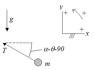
First, let's analyze the counterweight using a free-body diagram, as shown below.
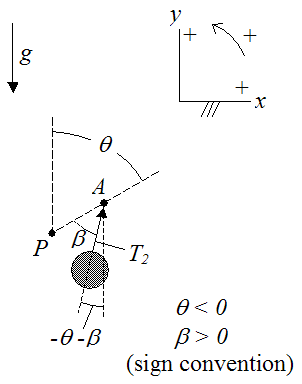
where T2 is the tension in the cable holding the counterweight.
Let the origin of the (fixed) coordinate system xy lie at point P (which is a fixed point).
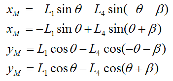
The coordinates of the counterweight M are given as:
The acceleration of the counterweight M is:
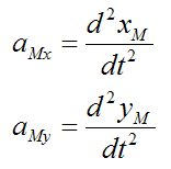
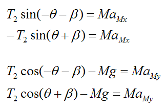
By Newton's Second Law,
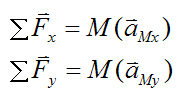
where M is the mass of the counterweight.
Therefore,
Next, let's analyze the beam using a free-body diagram, as shown below.
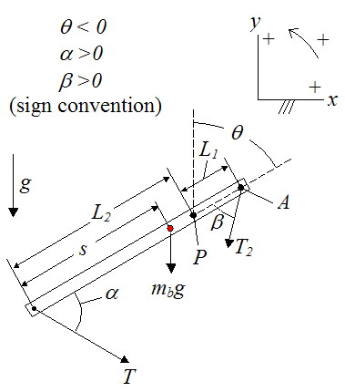
where T is the tension in the cable holding the payload, and mb is the mass of the beam. The weight of the beam mbg acts through the center of mass of the beam G.
Summing the moments about the pivot P we have:
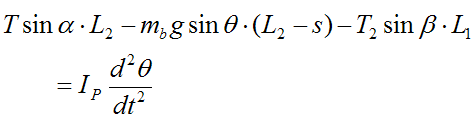
where Ip is the moment of inertia of the beam about an axis passing through point P and pointing out of the page. The term d2θ/dt2 is the angular acceleration of the beam.
By the parallel axis theorem,
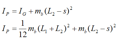
where IG is the moment of inertia of the beam about an axis passing through the center of mass G and pointing out of the page. In calculating the moment of inertia the beam is treated as a slender rod.
Lastly, analyze the payload using a free-body diagram, as shown below.
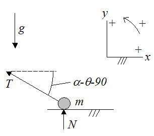
where m is the mass of the payload, and N is the normal force exerted by the guide chute on the payload.
Once again, let the origin of the coordinate system xy lie at point P (which is a fixed point).
Next, we need to define the position of the payload with respect to point P. To do this we set up a schematic as shown below.
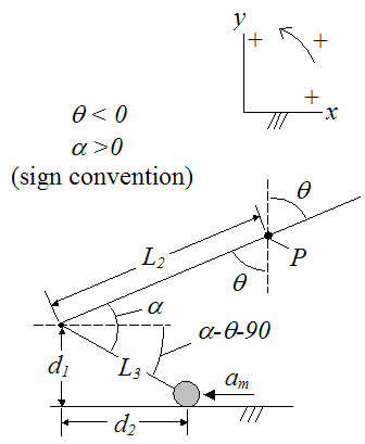
Where:
d1 is the vertical distance, as shown
d2 is the horizontal distance, as shown
am is the acceleration of the payload, as shown
Since the payload m is moving horizontally along the guide chute, only its x-coordinate (relative to point P) is changing. The x-coordinate (xm) is given by:
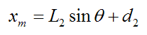
where
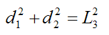
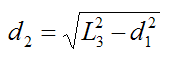
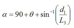
By geometry,
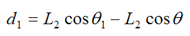
and
where θ1 is the angle the beam makes with the vertical when the payload end of the beam touches the guide chute (and the cable holding the payload is horizontal).
Thus, the acceleration of the payload is:
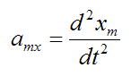
(There is no vertical component of acceleration, so amy = 0).
By Newton's Second Law,
where (by geometry),
The payload loses contact with the guide chute (lifts off) when the normal force N is zero. This means that the vertical component of tension T (in the y-direction) exceeds the weight of the payload (mg).
Case 2 – Payload Lifts Off From Guide Chute
In this case, the payload "lifts off" from the guide chute and experiences "unconstrained" motion, since it's no longer in contact with the guide chute. The analysis in this case begins with the following schematic.
The equations for the counterweight and beam are exactly the same as for the previous case (with the guide chute).
However, since the payload is unconstrained in this case (no contact with guide chute), its equations will be different from the previous case.
The free-body diagram for the payload m is shown below.
Just like before, let the origin of the coordinate system xy lie at point P (which is a fixed point).
The coordinates of the payload m are given as:
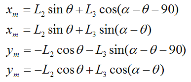
The acceleration of the payload m is:
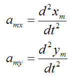
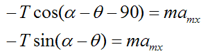
By Newton's Second Law,
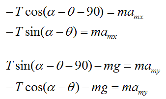
This completes the trebuchet physics analysis.
Return to The Physics Of Battle page
Return to Real World Physics Problems home page
Free Newsletter
Subscribe to my free newsletter below. In it I explore physics ideas that seem like science fiction but could become reality in the distant future. I develop these ideas with the help of AI. I will send it out a few times a month.