The Physics Of Bowling
Source: http://en.wikipedia.org/wiki/Bowling. Author: http://en.wikipedia.org/wiki/User:Xiaphias
Physics Of Bowling – The Bowling Ball
A bowling ball is made from urethane, plastic, reactive resin or a combination of these materials. Ten-pin bowling balls generally have three holes drilled into them; two finger holes and one thumb hole for gripping. For ten-pin bowling, regulating bodies allow for a maximum weight of 16 lb (7.2 kg), and a maximum diameter of 8.6 inches (21.8 cm) (ref: http://en.wikipedia.org/wiki/Bowling_ball).
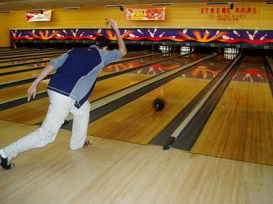
The physics of bowling discussed here will be with regards to ten-pin bowling, which is one of the most common sports in the game of bowling.
The figure below shows two ten-pin balls.
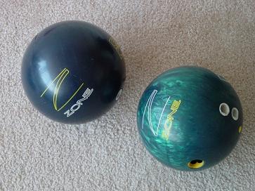
Source: http://en.wikipedia.org/wiki/Bowling_ball. Author: http://en.wikipedia.org/wiki/User:Ommnomnomgulp
Bowling Ball Interior
The bowling ball consists of a hard outer shell with a weight block in the core (the inside of the bowling ball). The mass and shape of the weight block affects the spin of the bowling ball and how it curves as it rolls down the lane. These play an important role in the physics of bowling and (consequently) a bowler's performance, as will be discussed.
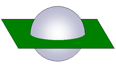
There are two basic types of weight blocks used, symmetric weight blocks and asymmetric weight blocks. To illustrate them, imagine cutting a bowling ball in half with an imaginary cutting plane (as shown below) so as to expose the full cross-section of the weight block inside the bowling ball.
The figure below shows the cross-section view for a symmetric weight block.
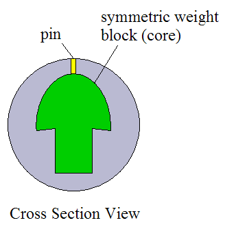
The weight block is molded into the bowling ball. The "pin" represents the topmost position of the weight block, as shown. This topmost position is closest to the outside surface of the bowling ball.
A symmetric weight block is called "symmetric" because it is axi-symmetric, meaning it has an axis of symmetry along its centerline. To illustrate, consider the figures below with a coordinate system xyz as shown. Note that point G represents the center of mass of the bowling ball.
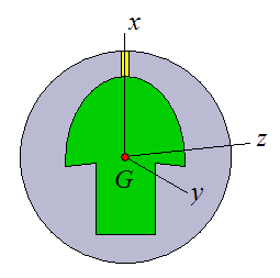
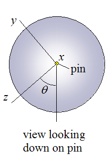
Let the plane x-z represent the imaginary cutting plane. For any angle θ the resulting cross-section view of the symmetric weight block would be the same. In other words, a symmetric weight block is axi-symmetric with respect to angle θ.
The figure below shows the cross-section view for an asymmetric weight block.
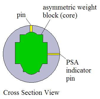
Just like the symmetric weight block, the "pin" represents the top position of the asymmetric weight block. However, an asymmetric weight block is not symmetric with respect to angle θ. And due to its non-symmetry, a "PSA indicator pin" is placed on the side of the weight block, at the point (or area) closest to the outside surface of the bowling ball. These two pins are located 90° from each other.
The "PSA indicator pin" is also called the "mass bias" location. This is simply a different naming convention in bowling terminology.
The pins allow one to determine the orientation of the weight block inside the bowling ball. A symmetric weight block only needs a single pin to define its orientation inside the bowling ball, but an asymmetric weight block needs two pins to define its orientation (due to its non-symmetry).
The pins give important information on where to drill the finger and thumb holes of the bowling ball so that the bowler can control the spin and curve of the ball, in order to make the best possible shot. This will be explained in more detail later on, as the physics of bowling is discussed in greater depth.
Bowling balls with symmetric and asymmetric weight blocks result in similar performance, but bowling balls with an asymmetric weight block allow for a bit more "tweaking" to get the ball to react a certain way when in motion. However, the physics of bowling is very similar whether the weight block is symmetric or asymmetric.
In addition to the pins, two other points of interest on a bowling ball are the Positive Axis Point (PAP) and the CG point. These directly relate to the physics of bowling and are shown in the figure below.
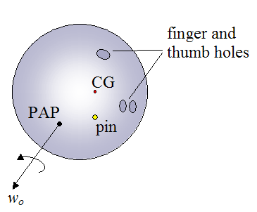
The PAP is the initial axis of rotation of the bowling ball as soon as it begins traveling down the lane. The orientation of this axis depends entirely on the bowler's release technique. It is unique to each bowler.
wo is the initial rotation speed (angular velocity) of the bowling ball. This also depends on the bowler's technique.
The figure below shows an imaginary line originating from the geometric center C of the bowling ball, and passing through the center of mass G of the bowling ball. The intersection of this line with the surface of the bowling ball is called CG. This point is useful because it gives information on the location of the center of mass G of the bowling ball.
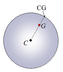
Note that the distance between C and G is greatly exaggerated for clarity. In reality, the distance between the two is very small and is typically less than 1 mm (ref: What Makes Bowling Balls Hook?, Cliff Frohlich, American Association of Physics Teachers, 2004).
Bowling Ball Motion
The optimal trajectory of a bowling ball is a curved path where it strikes the pins at an angle. Striking the pins at an angle improves the chances that there will be a "strike" in which all the pins are knocked down.
Analyzing the physics of bowling is very useful because it allows one to understand the factors that influence how the bowling ball curves, and how one can make the best possible shot when striking the pins.
If the ball follows a curved path, it will be able to strike the pins at a greater angle than a bowling ball that travels in a straight line. Therefore, controlling the degree of curve is essential to making the best possible shot.
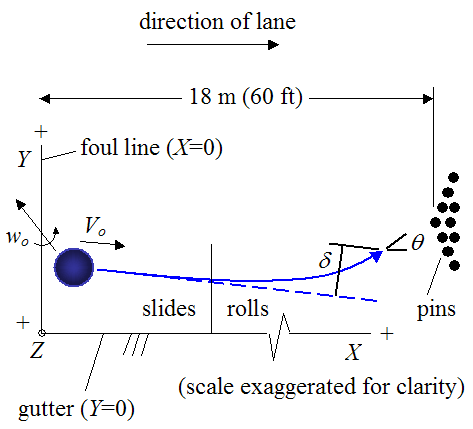
For ten-pin bowling the length of the lane is 18 m (60 ft). The lane is oiled to protect it from wear, especially during the initial sliding (skidding) stage of the bowling ball, before it begins pure rolling.
The bowler must make the shot behind the foul line and must avoid getting the ball into the gutter. The two figures below illustrate the motion of a bowling ball as it travels down the lane. The ball motion shown is typical for a right-handed bowler. For a left-handed bowler the motion is simply "mirrored" so that the ball curves towards the left gutter instead of the right gutter, before hitting the pins.
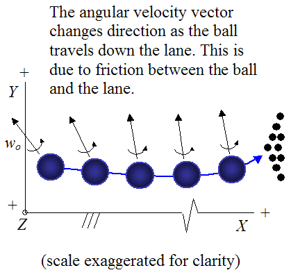
The ball begins rolling with a rotation speed (angular velocity) of wo and a linear velocity Vo.
Typically, during the first part of the motion the bowling ball slides along the lane, since its rotational speed does not match with the linear velocity of the ball. But eventually, lane friction stops the ball from sliding, and pure rolling begins. The ball then continues rolling until it hits the pins.
The ball hits the pins at an angle θ. The greater this angle, the more oblique the impact and the greater the chance that all the pins will be knocked down. The deflection δ is called "hook". It is the sideways deflection of the ball from the original (straight) trajectory indicated by the dashed blue line.
Ideally, the front-most pins are hit first by the bowling ball (at an oblique angle), since this will most likely result in a strike.
In order to model the physics of bowling, a (fixed) coordinate axes XYZ is chosen with the following orientation: The X-axis is aligned with the right gutter (parallel to the lane), the Y-axis is aligned with the foul line, and the Z-axis is vertical (perpendicular to the lane). This chosen coordinate system becomes relevant in the next section, where the physics is analyzed in depth.
The location of wo (PAP) relative to the pin location(s) on the bowling ball, is very important in influencing the amount of hook δ, and impact angle θ. Therefore, the finger and thumb holes must be positioned in an optimal way relative to the pin location(s), so as to optimize δ and θ, in order to get the best possible shot.
The location of CG relative to the PAP location also influences δ and θ, but to a much lesser degree, so it is not accounted for nearly as much when optimizing ball performance.
For each individual bowler, the PAP is (approximately) in a fixed location relative to the finger and thumb holes. For each individual bowler the position of the PAP relative to the finger and thumb holes, must be determined with a "test" ball. And once this relative position is determined, the finger and thumb holes are drilled in a new ball, so that the resulting PAP is in an optimal position relative to the pin location(s).
In a nutshell, the location of the PAP relative to the pins on the bowling ball determines how much the bowling ball precesses as it travels down the lane. Consequently, the level of precession is directly proportional to the level of friction between the lane and the bowling ball. The level of friction, in turn, has a large influence on δ and θ.
So in general, more precession leads to more friction and results in more hook, and less precession leads to less friction and results in less hook. This is one of the main criterion that all good players are aware of when calibrating their game for best performance.
The figure below illustrates precession, and how it affects the level of friction between the lane and the bowling ball.
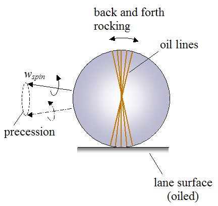
Precession is the change in direction of the bowling balls spin vector wspin, over time. For example, a spinning top (pivoted about a base) has two spin components. The first component is the main spin, which is the spinning of the top about its central axis. The second component is the secondary spin, which causes the orientation of the top to change so that its central axis goes around in a circle. This secondary spin component is called precession.
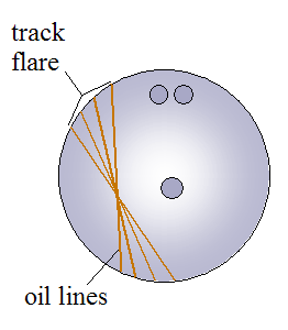
In the case of the bowling ball, precession causes a back and forth rocking (as shown) as it travels down the lane. This changes the contact surface after each full ball revolution, and thus increases the area of the ball in contact with the lane. This becomes evident by the various lines of oil (shown in the figure above) that the ball picks up from contact with the lane. The oil lines appear “flared out”, and the width of the flare (called "track flare") is a measure of the degree of rocking (due to precession). Each line of oil represents one full revolution of the ball as it travels down the lane.
Therefore, precession results in greater friction between the lane and the bowling ball, since the oil is "spread out" on the surface of the bowling ball in a larger area than if the ball did not precess. If the bowling ball did not precess, there would only be one oil line, and this would result in lower friction due to repeated lane contact with the same area of the bowling ball. Hence, precession results in a greater area of the bowling ball making contact with the lane, which results in lower oil accumulation on the ball per contact area, thus resulting in greater friction. This becomes most apparent on the "dry" (non oiled) part of the lane, which is typically the last third (or so) of the lane length. In this part of the lane, friction between lane and ball is most sensitive to the amount of oil accumulated on the ball per contact area (since the lane itself is dry). This means that precession raises the level of friction between lane and ball. Therefore, in the dry part of the lane a precessing ball will hook the most.
The figure below shows another illustration of the typical oil line pattern one might see on a bowling ball that has undergone precession.
As mentioned already, the position of the PAP relative to the pin locations determines how much the bowling ball precesses as it travels down the lane. In particular, we can specify the relative position of the PAP for bowling balls with symmetric and asymmetric weight blocks. This is a key factor in the physics, since it directly affects the motion of the ball as it travels down the lane. It is described next.
Bowling Balls With Symmetric Weight Blocks
If one wishes to have no precession, the PAP must be located at the topmost pin location or anywhere on the circumference around the middle of the bowling ball, represented by the dotted line, shown in the figure below.
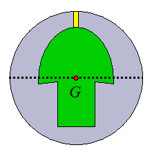
If one wishes to have precession, then the PAP must be located between these two locations - that is, between the topmost pin and the dotted line. Experienced ball drillers know where to place the PAP to get the desired amount of precession. To have maximum precession (maximum track flare) the PAP must be placed exactly in between the topmost pin and the dotted line, so that the distance from the PAP to the topmost pin is equal to the distance from the PAP to the dotted line.
In physics terms, an axis passing through G and the topmost pin location represents the minimum principal moment of inertia, and an axis passing through G and any point on the dotted line represents the maximum principal moment of inertia - this is due to the symmetry of the weight block.
Side note: Precession is a form of unstable rotation, and it occurs when the PAP does not coincide with the principal axes for the minimum or maximum moment of inertia.
For stable rotation (no precession), the PAP must coincide with the principal axes for the minimum or maximum moment of inertia.
Bowling Balls With Asymmetric Weight Blocks
If one wishes to have no precession, the PAP must be located at the topmost pin location or at the PSA indicator pin location on the side, as shown in the figure below.
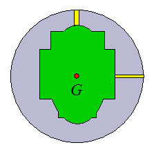
If one wishes to have precession, then the PAP must be located between these two locations - that is, between the topmost pin and the PSA pin. Experienced ball drillers know where to place the PAP to get the desired amount of precession. To have maximum precession (maximum track flare) the PAP must be placed exactly in between the topmost pin and the PSA pin, so that the distance from the PAP to the topmost pin is equal to the distance from the PAP to the PSA pin.
In physics terms, an axis passing through G and the topmost pin location represents the minimum principal moment of inertia, and an axis passing through G and the PSA pin represents the maximum principal moment of inertia - this is due to the asymmetry of the weight block. Note that PSA means "preferred spin axis" since the axis with the maximum principal moment of inertia is naturally the most stable axis of rotation for a rigid body.
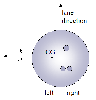
So far in discussing the physics of bowling, we have talked about the influence of PAP location and friction on ball motion. But there is another factor which influences ball motion, although not as much. It is the position of the CG. If the CG is on the left side of the bowling ball as it travels down the lane, the ball tends to hook a bit more (to the left), so it's beneficial. The figure below illustrates this.
Simulation For Different Friction Cases
The main influence on ball motion is friction between the ball and the lane, whether it's due to friction influenced by ball precession, or natural lane conditions (e.g. oiled vs. non-oiled).
Thus, we wish to look at three different cases of friction, in order to observe its effect on ball motion.
Let's assume that the initial angular velocity of the ball wo = 30 rad/s, and the initial linear velocity of the ball Vo = 8 m/s. This is a reasonable estimate for the typical bowler who averages 200 (ref: What Makes Bowling Balls Hook?, Cliff Frohlich, American Association of Physics Teachers, 2004).
Let's assume wo is pointing 15° to the left of the Y-axis, so that it has components wX = -30×sin 15° = -7.76 rad/s, and wY = 30×cos 15° = 28.98 rad/s.
And let's assume that Vo is pointing in the positive X-direction.
The beginning of the bowling balls trajectory is at X = 0.
The following additional input values are used with regards to the initial orientation, and properties of the bowling ball:
• The distance between the center of the bowling ball C and the center of mass G is 1 mm (0.001 m). The point CG is pointing in the positive Y-direction.
• The bowling ball has a symmetric weight block with the pin pointing in the positive Y-direction.
• The radius of the bowling ball is 10.85 cm.
• The mass of the bowling ball is 7 kg.
• The minimum principal moment of inertia is 0.031 kg·m2. This is the moment of inertia about an axis passing through the center of mass of the bowling ball G and the pin.
• The maximum principal moment of inertia is 0.033 kg·m2. This is the moment of inertia about any axis which passes through the center of mass of the bowling ball G and which is perpendicular to the axis corresponding to the minimum principal moment of inertia.
Lastly, the input value for the acceleration due to gravity (on earth's surface) is 9.8 m/s2.
The above input values will be held constant for the following three friction cases to be considered. In all three cases the static friction will be assumed sufficient enough to maintain pure rolling once pure rolling begins.
Friction Case 1
The coefficient of kinetic (sliding) friction is equal to 0.12. This value of kinetic friction will be taken as constant over the entire length of the lane, as illustrated below.
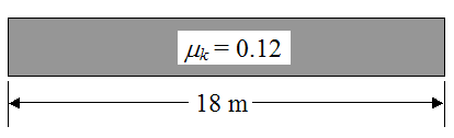
Simulation Results
The bowling ball slides 9 m before pure rolling begins.
The ball hooks to the left δ = 68 cm.
The impact angle θ is 3.6°
Friction Case 2
The coefficient of kinetic friction is equal to 0.08. This value of kinetic friction will be taken as constant over the entire length of the lane, as illustrated below.
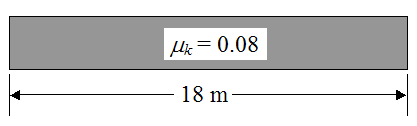
Simulation Results
The bowling ball slides 13.7 m before pure rolling begins.
The ball hooks to the left δ = 55 cm.
The impact angle θ is 3.3°
Friction Case 3
The coefficient of kinetic friction is equal to 0.04 for the first 12 m of the lane, and is equal to 0.2 for the remainder of the lane (the remainder of the lane is "dry", no oil). This is illustrated below.
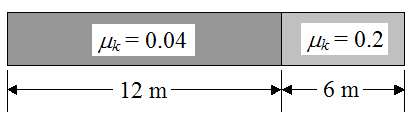
Simulation Results
The bowling ball slides 15 m before pure rolling begins.
The ball hooks to the left δ = 37 cm.
The impact angle θ is 3.3°
Looking at the three friction cases we can see that the greater the level of friction, the greater the ball hook. The impact angle also increases slightly with friction.
As mentioned before, when the bowling ball precesses, the effective friction between the lane and ball increases. However, in the simulation, the friction coefficient was input as constant values (independent of ball precession), so the dependence of friction on ball precession was not captured in the model (due to the difficulty in doing so). So, to approximate the effect of friction, the friction coefficient was varied over a range of values in order to observe the effect on ball motion, and it is reasonable that this will approximate the influence of friction on ball motion when friction is affected by ball precession.
Hence, the simulation results indirectly show that precession causes the bowling ball to hook more (since precession increases friction).
A Closer Look At The Principal Moments Of Inertia
In general, a rigid body has three distinct principal moments of inertia. It is useful to know the magnitude and direction of these three quantities because they simplify the equations for three-dimensional rigid body dynamics.
The shape of the weight block inside a bowling ball makes it fairly straightforward to determine the principal directions of inertia. If a rigid body has two or three planes of symmetry, the principal directions will be aligned with these planes. By inspection, one can usually find the symmetry planes in the weight blocks, and as a result easily determine the principal directions for them. Since the remainder (outer part) of the bowling ball is itself almost completely symmetric due to its spherical shape, the result is that the (entire) bowling ball has principal directions closely aligned with the principal directions of the weight block.
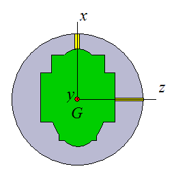
For example, consider a bowling ball with a symmetric weight block, as shown in the two figures below.
The minimum principal moment of inertia of the bowling ball is about the x-direction. Let's call this Ix. This is the minimum moment of inertia because the mass of the weight block is the least "spread out" about the x-direction. This is a result of the design of the weight block.
The y and z directions correspond to the principal directions of the remaining two principal moments of inertia. These two moments of inertia are greater than Ix because the mass of the weight block is most "spread out" about these directions. However, because of symmetry, these two principal moments of inertia are in fact equal (Iy = Iz). Furthermore, due to symmetry these two moments of inertia are constant for all angles of θ.
Now, consider a bowling ball with an asymmetric weight block, as shown in the figure below.
Once more, the minimum principal moment of inertia of the bowling ball is given by Ix because the mass of the weight block is the least "spread out" about the x-direction.
The maximum principal moment of inertia is given by Iz because the mass of the weight block is most "spread out" about this direction. The remaining principal moment of inertia is given by Iy (pointing out of the page). Due to the non-symmetry of the weight block all three principal moments of inertia are distinct.
In physics, the moment of inertia (I) is sometimes defined as I = (mass)×(radius of gyration)2. So for a body of given mass, a higher radius of gyration results in a greater moment of inertia (by definition).
In bowling terminology, the radius of gyration is called the "RG value", and the term "RG differential" refers to the difference between the maximum and minimum moment of inertia of a bowling ball (i.e. Imax − Imin).
In bowling lingo: The greater the "RG differential", the greater the potential for a bowling ball to create "track flare", and the greater the hook potential. Translated into physics lingo this means: The greater the difference Imax − Imin, the greater the potential for precession. As a result, there is a greater potential for friction between ball and lane, and a greater potential for the ball to hook.
However, bowling regulations limit the amount of "RG differential" in a bowling ball.
Of course, whether or not this hook potential is fully utilized depends on where the PAP is placed relative to the pin locations on the bowling ball.
Physics Of Bowling – Model Description
I created a numerical model in Excel which captures the physics of bowling and simulates the motion of a bowling ball as it travels down the lane. A time step of 0.0001 seconds was used to ensure sufficient numerical accuracy. It was a challenging and time consuming task to develop this model, but the result is that I am able to accurately capture the essential physics behind bowling, without any gross simplifications and shortcuts which sacrifice accuracy.
To download the Excel spreadsheet right-click on this link.
I'm making the spreadsheet available, and the instructions to use it, for free. The download file is in compressed "zip" format. You need to uncompress this file before you can use it.
To use the bowling simulator you need to have Microsoft Excel installed on your computer. The program is compatible with all versions of Excel.
The development of the equations to fully analyze the physics behind bowling is quite an onerous task both to derive and fully present on a website. Therefore, the full mathematical development will not be presented here. Instead, the basic equations will be introduced in order to give the reader a basic understanding of the core physics and mathematics required.
For those interested, I provide PDF files of my handwritten equation development that show the full equations used in the Excel simulator. The first file is the full equation development, and the second file is a general linear equation solution used for the Excel simulator at each time step. They are messy and will be hard to understand, but will be useful for those willing to work through the math.
The following assumptions are made in the model:
• The lane is perfectly flat.
• Friction is proportional to normal force, and the coefficient of friction between ball and lane is constant.
The figure below illustrates the full set up for analyzing the physics, with (fixed) global coordinate system XYZ as shown, along with sign convention.
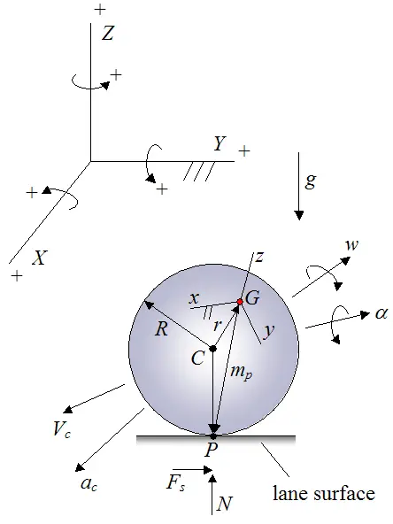
Where:
C is the geometric center of the bowling ball
R is the radius of the bowling ball
G is the center of mass of the bowling ball
r is the vector from point C to point G. This vector is very short, usually less than 1 mm in length
P is the contact point between the bowling ball and the surface of the lane
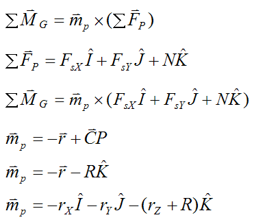
mp is the vector from point G to point P
xyz is the local coordinate axes fixed to the bowling ball, so that it moves with the bowling ball. The orientation of xyz is such that it is aligned with the principal moments of inertia of the bowling ball.
w is the angular velocity of the bowling ball
α is the angular acceleration of the bowling ball
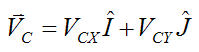
Vc is the linear velocity of the geometric center of the ball C. This is also considered to be the linear velocity of the bowling ball
ac is the linear acceleration of the geometric center of the ball C. This is also considered to be the linear acceleration of the bowling ball
Fs is the friction force acting on the bowling ball, due to contact between the ball and lane. This force is parallel to the lane surface
N is the normal force pushing up on the ball, perpendicular to the lane surface
g is the acceleration due to gravity, acting downwards. This value is equal to 9.8 m/s2 on earth
Defining the orientation of xyz at any point in time
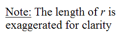
To define the orientation of xyz with respect to the (fixed) global XYZ axes, we must first set up the basic equations for the vectors x, y, and z in terms of direction cosines.
Thus,
Where:
x, y, and z are unit vectors
l1, m1, n1 are the direction cosines corresponding to the unit vector x
l2, m2, n2 are the direction cosines corresponding to the unit vector y
l3, m3, n3 are the direction cosines corresponding to the unit vector z
I is the unit vector pointing along the positive direction of global X
J is the unit vector pointing along the positive direction of global Y
K is the unit vector pointing along the positive direction of global Z
By definition, the orientation of I, J, K remains constant, since XYZ is fixed in space.
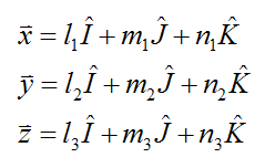
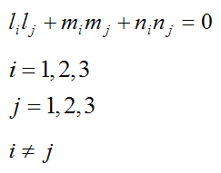
Since x, y, and z are unit vectors,
and since x, y, and z are perpendicular to each other (by definition),
Defining the orientation of vector r at any point in time
Similar to before, the orientation of r is with respect to the (fixed) global XYZ axes:
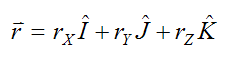
Where:
rX is the component of r along the global X-direction
rY is the component of r along the global Y-direction
rZ is the component of r along the global Z-direction
Defining the orientation of angular velocity w and angular acceleration α at any point in time
Similar to before, the angular velocity and angular acceleration are vectors expressed relative to the (fixed) global XYZ axes. They are given by
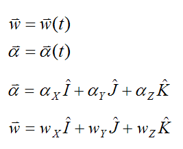
Where:
t is time
αX is the component of α along the global X-direction
αY is the component of α along the global Y-direction
αZ is the component of α along the global Z-direction
wX is the component of w along the global X-direction
wY is the component of w along the global Y-direction
wZ is the component of w along the global Z-direction
Thus, the angular velocity and angular acceleration of the bowling ball are always with respect to (fixed) ground.
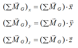
Determining the components of the angular velocity w and angular acceleration α along the xyz axes
It's necessary to resolve the angular velocity and angular acceleration into their components along the xyz axis. This can be done using the vector dot product (a⋅b):
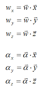
Therefore,
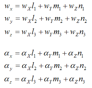
where the subscripts x, y, and z (for the angular velocity and angular acceleration) denote their components along the x, y, and z directions, respectively.
Using forward integration to solve for the vectors w, r, and the orientation of xyz as a function of time
Let Δt be a small time step.
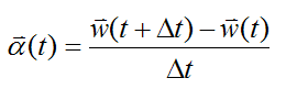
Forward integration is used to solve the physics equations. In this model, various unknown quantities at a new time t+Δt are calculated based on previous known quantities at time t.
For instance, we can solve for w(t+Δt) using the following equation for angular acceleration:
Similarly, we can find the new orientation of xyz at time t+Δt based on its previous orientation at time t:
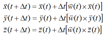
where a×b represents the vector cross product.
Similarly, for the vector r:
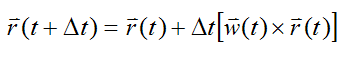
Note that the above expressions for x, y, z, and r incrementally increase their vector lengths (magnitudes) for each time step. Therefore, we must normalize the vectors x, y, z, and r after each time step to preserve their length (magnitude). This normalizing operation can be expressed mathematically as follows:
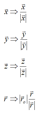
where ro is the length of the r vector calculated from its original specification (at time t = 0).
The acceleration of the center of mass G
The center of mass G is offset from the geometric center of the bowling ball C. Therefore we must calculate the acceleration of G as follows:
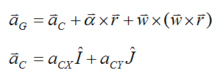
Where:
aG is the acceleration of the center of mass G
aCX is the global X-component of the acceleration of point C
aCY is the global Y-component of the acceleration of point C
Application of Newton's Second Law
The external forces acting on the bowling ball are gravity and the contact forces at point P. Therefore, we can express the sum of the forces on the bowling ball as:
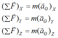
Therefore,
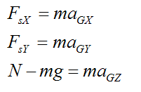
Where:
m is the mass of the bowling ball
FsX is the global X-component of the force acting on the bowling ball at point P
FsY is the global Y-component of the force acting on the bowling ball at point P
aGX is the global X-component of the acceleration of point G
aGY is the global Y-component of the acceleration of point G
aGZ is the global Z-component of the acceleration of point G
Sum of the moments (torque) acting on the bowling ball
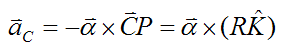
If we take the sum of the moments about the center of mass G, the only forces to account for are those acting at the contact point P, with vector arm mp. (The force of gravity exerts no moment about point G since its line of action passes through point G).
We can thus apply the Euler equations of motion for a rigid body:
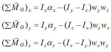
where Ix, Iy, and Iz are the principal moments of inertia, and
and
Note that the sum of moments in the Euler equations are expressed with respect to the local x, y, and z directions. It is necessary to do this when using these equations.
Lastly, we must consider two separate cases of ball motion when analyzing the physics. The first case involves kinetic (sliding) friction, where the bowling ball skids along the lane. The second case involves static friction, where the bowling ball has stopped skidding and is in a state of pure rolling.
Case 1 – Kinetic Friction
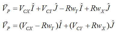
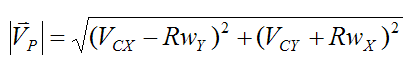
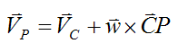
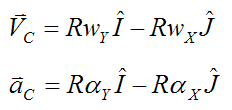
For this case, there is relative motion between the bowling ball and the lane at point P. We can express this relative motion as velocity VP, where:
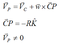
Now,
Where:
VCX is the global X-component of the velocity of point C
VCY is the global Y-component of the velocity of point C
Therefore,
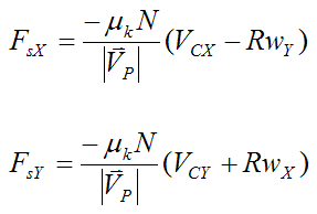
The magnitude of kinetic friction is given as
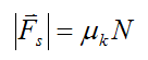
where μk is the coefficient of kinetic friction.
Kinetic friction acts opposite the direction of (relative) motion, therefore
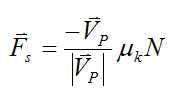
where
The components along the X and Y directions are:
Case 2 – Static Friction
For this case, there is no relative motion between the bowling ball and the lane at point P. Therefore, VP = 0.
Using the same expression as before,
Since VP = 0,
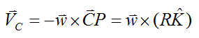
Similarly,
Therefore,
For pure rolling of the bowling ball the following condition must be satisfied:
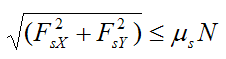
where μs is the coefficient of static friction.
This completes the analysis of the physics of bowling.
Return to The Physics Of Sports page
Return to Real World Physics Problems home page
Free Newsletter
Subscribe to my free newsletter below. In it I explore physics ideas that seem like science fiction but could become reality in the distant future. I develop these ideas with the help of AI. I will send it out a few times a month.