Stirling Engine
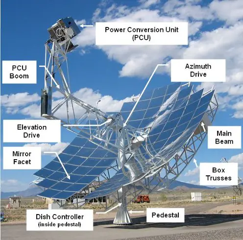
Stirling Engine Solar Dish. Source: http://www.stirlingenergy.com
Background
The Stirling engine has attracted much attention over the years. Its potential for high efficiency and the ability to use a wide variety of fuels has made it a serious contender for alternative power sources, especially in automotive applications. The potential for these engines to replace the Internal Combustion engine (ICE) in automobiles was explored in the late 1970’s and 1980’s.
In 1986 a technical report was released by NASA outlining the development of the MOD I, and MOD II automotive engine (ref: http://ntrs.nasa.gov/archive/nasa/casi.ntrs.nasa.gov/19880002196_1988002196.pdf). The engine used Stirling technology. It used pressurized hydrogen as the working gas. It was developed and produced by a collaborative effort between NASA and MTI (Mechanical Technology Incorporated). The MOD II engine in particular could reach a thermal efficiency of 38.5% (significantly higher than a spark ignition ICE), and with power comparable to an ICE of the same size (83.5 hp). It burned fuel with cleaner emissions than an ICE due to the fact that it burns fuel externally to the engine. It also produced much less noise during operation. Therefore, no muffler or catalytic converter would be needed for the tailpipe.
The technical problems were for the most part related to the high-pressure requirements of the engine (up to 15 MPa), which requires bulky components and specialized seals. Nevertheless it was projected that the cost of production due to economics of scale would be competitive with an ICE. Unfortunately, it failed to attract large investment in the automotive industry mainly because it was still in its infancy development-wise, and it couldn't compete with an ICE on the basis of responsiveness. Stirling engines do not respond as quickly to changes in power requirements as an ICE and take longer to warm up before reaching full power. Great strides could be made in solving this dilemma by using elaborate control systems regulating pressure, etc. But in the words of the large automakers such as GM, the market “would not tolerate this”, even though efficiency gains and reduction in harmful tailpipe emissions were significant. Furthermore, cheap energy (oil) was abundant and no one at the time cared to invest heavily in an engine deemed “economically risky”.
And now here we are today, faced with an energy future which can no longer blindly rely on fossil fuels to satisfy our needs. Conservation is becoming more important as well as alternative sources of energy. The Stirling engine is one of the possibilities for weaning ourselves off fossil fuels, given that it can use any source of heat to run, including biomass and solar. It is becoming clear that interest in this type of engine isn’t going to go away. In fact, there is growing interest.
Stirling Engine Basics – What is a Stirling Engine?
A Stirling engine is a heat engine that works on the basis of an external applied temperature difference. By maintaining a hot and cold temperature difference the engine is able to run and produce mechanical power. It is different from the Internal Combustion Engine (ICE) in that it is a closed cycle; that is, the working gas is enclosed (sealed) inside the engine. This is in contrast to the ICE in which the working gas (air) is drawn in from the environment, combusted with fuel, and expelled as exhaust. In such an engine valves and timing mechanisms are necessary. But in a Stirling engine, no such components are required. In addition, the Stirling engine is not restricted to the type of fuel used. It is indifferent to the source of heat, which opens up many possibilities, including non-polluting solar energy, or the burning of biomass (wood, husks, ethanol, etc), which are carbon-neutral. Carbon-neutral means they absorb as much carbon dioxide (during their growth - due to photosynthesis) as they emit when burned. This is unlike fossil fuels, which add a net amount of carbon dioxide to the atmosphere when burned.
The basic principle of the Stirling engine is this. The engine is filled (under pressure), with a gas such as air, helium, or hydrogen. This is called the “working gas”. Inside the engine the gas is heated. This increases its pressure and moves pistons as a result. The gas is then cooled, lowering its pressure. It is then heated again, and the cycle repeats. In a real engine this typically happens very fast, on the same order of speed as an ICE. The working gas is shuttled back and forth very quickly inside the engine, between the hot and cold ends, continuously gaining and losing heat and producing power as a result.
The working gas inside the engine is heated with a heater, and cooled with a cooler.
The heater and cooler are typically compact heat exchangers consisting of narrow tubes (or passageways) in which the working gas flows. It is through these passageways that the working gas either gains heat (becoming hotter), or loses heat (becoming cooler).
The outside surface of the heater is exposed to a source of high temperature, such as the flame of a burner, or concentrated solar energy. The outside surface of the cooler is exposed to a source of cold temperature such as ambient air, or water.
In between the heater and cooler is a regenerator. A regenerator increases the efficiency of a Stirling engine by lowering the heat input requirement of the heater and the heat removal requirement of the cooler. It is not necessary to have a regenerator for the engine to run but in the interest of cost-reduction, especially where the cost of heater fuel is concerned, it is wise to have one.
The way the regenerator works is by storing some of the heat energy of the working gas as it moves from the heater to the cooler, thereby reducing the cooling demand on the cooler. And on the return path, as the working gas moves from the cooler to the heater, it “gains” back some of that heat energy, thereby reducing the heating requirement of the heater. A regenerator basically pre-heats the working gas before it enters the heater, and pre-cools the working gas before it enters the cooler.
The regenerator is usually made of an intricate matrix material, made of stacked metal screens or metal felt, woven from fine wire. This provides the large surface area necessary for efficient heat exchange with the working gas.
In general, when designing Stirling engines for high power and efficiency there are several main factors, which must be addressed:
(1) Keep dead volume to a minimum. Dead volume decreases engine power. Dead volume is the volume that is “unswept” by the motions of the pistons. This is the volume contained in the heater, cooler, regenerator, and all the clearance spaces. This volume is constant at all times.
(2) Design the heater to maximize heating of the working gas, i.e. once the gas exits the heater its temperature must be as close as possible to that of the heater walls. This can be accomplished by using narrow and long tubes/passageways for the gas to flow through.
(3) Design the cooler to maximize cooling of the working gas, i.e. once the gas exits the cooler its temperature must be as close as possible to that of the cooler walls. This can be accomplished by using narrow and long tubes/passageways for the gas to flow through.
(4) Design the regenerator to maximize heat exchange with the working gas. This can be accomplished by using a sufficiently dense matrix material with large surface area.
(5) Keep pumping losses to a minimum. Pumping losses are the friction (flow) losses caused by the working gas as it “pushes” through the narrow tubes/passageways of the heater and cooler, and the regenerator matrix. Minimizing these losses can be accomplished by using a large number of tubes/passageways in the heater and cooler, and a regenerator with a large volume.
Now, points (2) - (5) can all be satisfied at the same time. However, satisfying these points is in direct conflict with point number (1). If one wishes to keep dead volume as small as possible they will have difficulty designing a good heater, cooler, and regenerator while keeping pumping losses low.
The solution is to compromise somewhat on all five points in order to achieve the best design possible. The challenge is to find the optimal balance resulting in the best engine design.
The Three Stirling Engine Configurations
There are three standard configurations for Stirling engines. They are: ‘alpha’, ‘beta’, and ‘gamma’ engines.
Alpha Engine
The figure below shows a standard alpha engine.
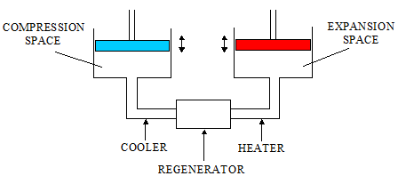
The working gas inside the engine is repeatedly “shuttled” back and forth between the expansion and compression space, due to the up-and-down motion of the two pistons. This repeatedly forces the working gas back and forth through the heater, regenerator and cooler. As a result, the gas is repeatedly heated and cooled, and power is produced.
Alpha engines are the simplest to understand, and are the easiest to construct. It’s also easy to minimize the dead (clearance) volume in the expansion and compression spaces. But one of their main disadvantages is that they can require temperature resistant seals for the piston exposed to high temperature (shown on the right). The seals for the other piston (on the left) don’t have to be temperature resistant because it is constantly exposed to cool temperatures, due to its physical proximity to the compression space.
Beta Engine
The figure below shows a standard beta engine.
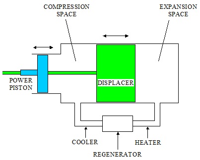
Beta engines are compact in size. They use a power piston and displacer, which are in line with each other. Unlike an alpha engine that uses two pistons, the beta engine uses one power piston and displacer. The purpose of the power piston is to generate power, while the purpose of the displacer is to move the working gas back and forth through the heater, regenerator, and cooler. As a result, the pushing force experienced by the displacer is very little compared to that of the power piston.
The power piston, displacer, and displacer rod are sealed around their gaps to prevent the leakage of working gas. The seal for the displacer is placed on the end closest to the compression space, in order to avoid direct contact with the hot working gas (in the expansion space). As a result, this seal does not need to be temperature resistant. The seals for the displacer rod and power piston do not need to be temperature resistant either since they are constantly exposed to cool engine temperatures. This is due to their physical proximity to the compression space.
A disadvantage of the beta engine is that it can be difficult to minimize the dead (clearance) volume in the expansion and compression space, given that there must be enough clearance to allow the working gas to “feed in” unobstructed from the heater and cooler.
Gamma Engine
The figure below shows a standard gamma engine.
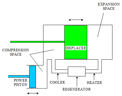
Gamma engines are the same as beta engines, except that the power piston is “shifted” down. This can make it easier to construct the mechanical drive and linkages since the power piston and displacer are a certain distance apart (instead of aligned with each other). For this reason, the gamma configuration is often the preferred choice by Stirling engine enthusiasts.
A disadvantage of the gamma engine is that it unavoidably introduces dead volume in the compression space due to the physical separation of the displacer and power piston.
Stirling Engine Efficiency
The potential efficiency of a Stirling engine is high. It is comparable to the efficiency of a diesel engine, but is significantly higher than that of a spark-ignition (gasoline) engine.
One of the most efficient Stirling engines ever made was the MOD II automotive engine, produced in the 1980′s. It reached a peak thermal efficiency of 38.5%. Compare this to a modern spark-ignition (gasoline) engine, which has a peak efficiency of 20-25%.
Despite its greater fuel economy, the MOD II engine was discontinued due to high development cost, and concerns that it would not compete with Internal Combustion engines (gasoline and diesel) in terms of responsiveness.
Miscellaneous Information About Stirling Engines
• The engine components that are exposed to high heat are generally made of stainless steel. These include: 1) expansion space piston (in alpha engines), 2) expansion space cylinder, 3) displacer (in beta and gamma engines), 4) heater, 5) regenerator matrix, 6) regenerator housing.
• The best working gas to use for achieving high power and thermal efficiency is hydrogen. Helium is the second best. However, helium is probably the safer choice, especially for those not wishing to take “explosive” risks.
• The Ideal Stirling cycle is very different from the cycle for practical (real) engines. In many descriptions of Stirling engines a single working space is given, and the thermodynamic analysis follows from that. The working gas is expanded and compressed using a single piston. And the heating and cooling takes place at the outside surface. Although it works well as a basic description of the Stirling cycle, this analysis cannot be directly applied to real power-producing engines. In a real engine you need a separate expansion and compression space, in which the working gas is shuttled back and forth through heat exchangers. This is the only way to enable the rapid heating and cooling of the working gas necessary for high-power engines, operating at high speeds. Therefore, the Ideal cycle analysis cannot be used to model real engines.
• The real engine will always have some leakage, however small. If using air as the working gas you can have a small compressor to maintain engine pressure. If using a gas such as hydrogen or helium it’s best to use a high-pressure storage tank to maintain pressure. Once the engine pressure drops below a certain value the tank releases gas into the engine until pressure is restored. If hydrogen is used one can even have an electrolysis device, which can produce hydrogen from water using electricity. This makes it easy to replace gas that has leaked.
• When using oil for lubrication, make sure that it doesn’t seep into the engine. The heat and pressure inside the engine will evaporate the oil and quickly foul the heat exchangers as a result. To combat this, some pistons use a combination of different seals, both to prevent gas from leaking out of the engine and to prevent oil from seeping in.
• When using biomass as heating fuel for the heater (such as wood chips or switchgrass), one must be careful of ash buildup on the heater tubes. The airborne ash can melt due to the high temperature, and form an insulating layer on the heater tubes, preventing heat from getting through. This will kill performance. This can be prevented with a gasifier-burner unit, which converts the biomass to combustible gases, which burn cleanly and won’t foul the heat exchanger.
• If water is used as the cooling medium for the cooler, it is typically mixed with antifreeze, especially if the engine is exposed to colder climates.
• There are two types of drive mechanisms for Stirling engines. The first type is kinematic, in which the piston and displacer motions are prescribed; meaning they are connected to linkages and crankshaft which in turn are connected to say, a generator. The other type is free-piston, in which there are no linkages and crankshaft connected to the piston and displacer. This allows, for example, the generator to be connected directly to the piston, and is directly actuated by its back-and-forth motion. The former type of drive mechanism is more common, although the latter allows for a perfectly hermetic seal in which a generator (such as a linear alternator) can be completely sealed inside the engine, resulting in virtually no leaking of working gas.
• One way to significantly improve thermal efficiency in the design is to improve the heat transfer efficiency from heat source to heater tubes. A common loss mechanism in this regard is heat loss to the surrounding environment (e.g. warm exhaust from a burner). A way to minimize this loss is with an air Preheater. Using the exhaust stream, a Preheater heats the air before it enters the combustion chamber, and more of the heat energy of the fuel is used. This is also more economical since it reduces fuel consumption. In addition, you can also minimize heat loss by placing an insulated enclosure around the heat source.
• A well-designed heat source, such as burner with air Preheater, can have a heat transfer efficiency of 90%. This means that 10% of the heat is lost to the environment. This loss further reduces thermal efficiency by several percent. For example, an engine operating at 40% thermal efficiency with (theoretically) perfect heat transfer from the heat source, would run at 36% efficiency with 90% heat transfer efficiency (0.90x0.40).
Additional information on Stirling engines is available in an information manual I created for my Stirling engine software program. I also have an information page on low temperature Stirling engine design.
Return to Engineering page
Return to Real World Physics Problems home page
Free Newsletter
Subscribe to my free newsletter below. In it I explore physics ideas that seem like science fiction but could become reality in the distant future. I develop these ideas with the help of AI. I will send it out a few times a month.