About me and why I created this physics website.
Tube Bending
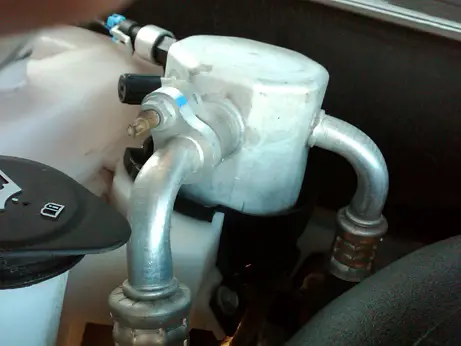
Bent Tubes. Source: http://en.wikipedia.org/wiki/Tube_bending. Author: http://en.wikipedia.org/wiki/User:Jokazi
Tube bending is a general term used to describe the metal forming process used to permanently form tube or pipe. For my Master's degree project I researched rotary draw tube bending which is a common method used to bend tubes. I also studied the physics of bending tubes and developed a computer program to predict the stresses, strains, wall thickness, and springback of a tube after bending. The computer model also estimates the force and torque required to bend tubes to a given radius. Having the means to predict tube geometry after bending is useful as a manufacturing aid since it can reduce trial and error during prototyping. This of course, reduces time and costs.
The figure below illustrates a rotary draw tube bending process along with the names of the tooling used.
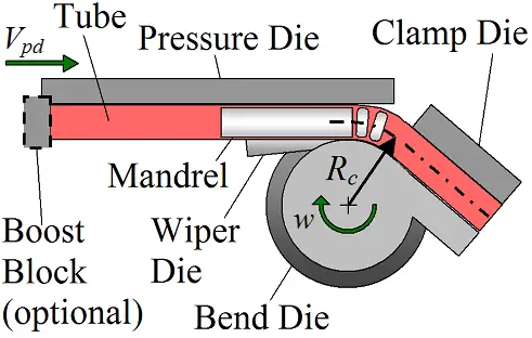
To bend a tube in a rotary-draw bender, it is first positioned inside the bender. It is then locked in place by closing of the clamp die onto the bend die. With the tube in place, the bend die and clamp die then rotate around as one piece, bending the tube around the bend die, with the pressure die maintaining pressure against the wiper, and moving along in the axial direction at a prescribed percent boost. The rotation is continued until a desired tube bend angle is reached. To control the axial tube motion, the pressure die applies axial force to the tube either through friction (between pressure die and tube) or through an optional boost block (as shown), which pushes against the back of the tube during bending.
The role of the pressure die is two-fold. First, it must exert sufficient clamping pressure by pushing the tube against the wiper die (inclined at a small rake angle) to prevent wrinkling on the inside bend of the tube, and secondly it must control the axial movement of the back of the tube feeding into the bend.
The mandrel helps to prevent wrinkles and ovalization of the tube during bending.
The percentage boost is also called an axial assist. It "forces" material into or out of the bend as a way to control the wall thickness and strains imparted onto the tube during bending. The percentage boost is the ratio of the instantaneous linear velocity of the pressure die (Vpd), to the instantaneous tangential velocity of the rotating bend die, at tube centerline radius Rc. The tangential velocity of the bend die, at radius Rc, is equal to Rcw, during the bend, where w is the angular velocity of the bend die as it rotates. This ratio is then converted into a percentage and this is called "percent boost". The level of boost controls the movement of the back of the tube feeding into the bend, which affects the thickness and strains generated in the tube during bending.
The percentage boost is the primary controllable factor affecting the wall thickness and strain of a tube due to bending, hence its usefulness. One of the most useful features of the computer program I created is that it can predict the wall thickness and strain of a tube after bending, for a given percent boost. Based on experimental results for a ratio of Rc/d = 2 and 2.5 (where d is the outside tube diameter), the wall thickness predictions by the computer program are accurate within ±10%, and the axial strain predictions are accurate within ±25%.
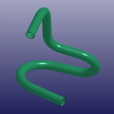
This computer program is not as accurate as a finite element analysis (FEA), but the main advantage of using it instead is that it runs much faster than a FEA analysis (up to 500 times faster) and is much easier to set up. It can also be used to generate a finite element mesh of a tube with any number of bends, for possible use in a secondary forming simulation (such as hydroforming) using LS-DYNA. The figure below shows a picture of a bent tube with geometry generated by the computer program, and viewed with LS-PrePost, which is a post-processor that is available with LS-DYNA.
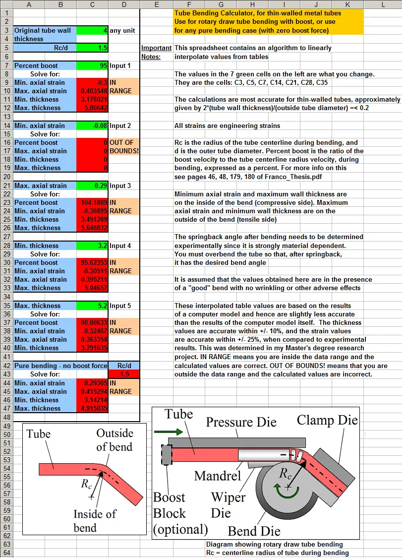
In addition, I created a tube bending calculator in Microsoft Excel. This calculator uses data points generated by the computer program, and uses linear interpolation to calculate bend parameters (based on these data points), such as minimum/maximum wall thickness, and minimum/maximum axial strain of a tube after bending. These parameters depend upon the tube dimensions and the percent boost, which serve as input into the calculator. The Excel spreadsheet calculates values for Rc/d over the range 1-6, using 10 data tables spread apart over this range. This gives good data point resolution. (Note that Rc is the tube centerline radius, and d is the outside tube diameter).
The advantage of using this Excel based calculator instead of the computer program is that it is easier to use and outputs results instantly without having to "run".
The values calculated in the spreadsheet are valid for any metal tube. These values are almost entirely independent of the specific material properties of the tube. However, certain calculations such as residual stresses, boost force, bending torque, and springback angle, are not given by the calculator since they are strongly material dependent and thus can only be done by running the computer program.
This tube bending calculator is useful both for rotary draw tube bending predictions, and for predictions involving pure bending cases which have no axial assist (i.e. no boost force). The pure bending case is common with, say, home (or DIY) tube benders, which hobbyists often use to bend tubes for various applications. There is a section in the tube bending calculator which calculates minimum/maximum wall thickness, and minimum/maximum axial strain for tubes undergoing pure bending.
To use the calculator you need to have Microsoft Excel installed on your computer. The program is compatible with all versions of Excel.
Click on this link to see a screen capture of the Excel spreadsheet.
The tube bending calculator is available for download through this link.
All the files that come with this calculator are contained in a single (compressed) file, in the "zip" format. You need to uncompress this file before you can access it.
I'm also including my Master's thesis with this download, which goes into great detail on the rotary draw tube bending process, and the physics behind the computer program used to model it.
Return to Engineering page
Return to Real World Physics Problems home page