About me and why I created this physics website.
Slingshot Physics
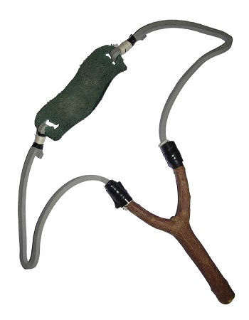
Source: https://commons.wikimedia.org/wiki/File:Slingshot_%28weapon%29.jpg. Author: https://commons.wikimedia.org/wiki/User:Yug
Slingshot physics involves the use of stored elastic energy to shoot a projectile at high speed. This elastic energy comes from rubber bands which are specially made for slingshots. This energy is provided initially by the muscle energy of the slingshot operator. One of the goals of a slingshot is to fire the projectile at the greatest speed possible. To do this two basic physics conditions must be satisfied. First, you must maximize your draw length, and second you must maximize the draw force you can personally exert over the draw length. In other words, the slingshot must be designed (for you) such that you are able to pull back on the projectile as far as you can and as hard as you can, before releasing it. This maximizes the elastic energy stored in the rubber bands which translates into the maximum kinetic energy of the projectile upon release, which results in the maximum release speed of the projectile. This in turn results in the greatest impact energy, and therefore damage inflicted on the target when it is struck by the projectile.
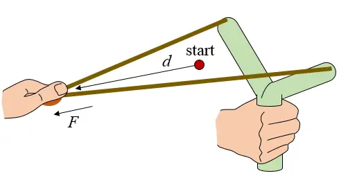
The figure below shows a conventional Y-shaped slingshot. The red dot represents the position at which the rubber bands start being pulled (drawn). At this point there is no tension in the rubber bands. Due to the slack in the rubber bands this start position lies ahead of the plane of the Y-shaped fork. The distance d represents the draw distance and the force F represents the draw force. Due to the slack in the rubber bands the distance d can be less than the maximum draw length of the person operating the slingshot. The red dot also represents the approximate release point of the projectile since it is the point at which the rubber bands no longer "pull" on the projectile. At this point the rubber bands have returned to their initial unstretched length and all their stored energy has (in theory) been given to the projectile. In reality though, a fraction of the energy is always lost through internal and external friction. Naturally we want to keep this fraction of energy loss as small as possible.
When pulling back on the rubber bands the draw force F increases as the draw distance d increases, just like when a spring is stretched. Ideally we want the maximum draw force (Fmax) of the person operating the slingshot to be at the point at which his/her draw length is a maximum (dmax). This results in the maximum amount of energy stored in the rubber bands (provided by the slingshot operator), and therefore results in the most powerful shot. To achieve this ideal situation a rubber band made of appropriately selected material would have to be used which matches the strength limits of the slingshot operator. However, this is not necessarily practical.
The figure below illustrates the draw force F as a function of draw distance d for a conventional Y-shaped slingshot.
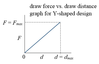
The energy stored in the rubber bands, and delivered to the projectile (assuming zero energy loss), is given by the area under the curve, which is given by E = (1/2)dmaxFmax, where E is the stored energy. Assuming zero energy loss, this energy is equal to the kinetic energy of the projectile upon release, which is given by E = (1/2)MV2, where M is the mass of the projectile and V is the speed of the projectile upon release. Equating stored energy with kinetic energy we have the equation dmaxFmax = MV2. Note that we are ignoring the mass of the rubber bands and pouch in this equation, which is a reasonable assumption for the cases where the projectile has a much greater mass than the combined mass of the rubber bands and pouch. Also note that the above figure shows a linear relationship for the draw force versus draw distance. This is not necessarily the case. In reality there may be a non-linear relationship between draw force and draw distance. Nevertheless, the stored energy is still the area under the curve, which for non-linear functions can be determined using integral calculus.
Other slingshot designs are certainly possible, such as the W-shaped slingshot shown in the figure below. I first saw this design when watching the really cool JoergSprave channel on YouTube. This design is similar to the Y-shaped design in that the rubber bands are initially slack at the start of the draw (d = 0). Once more, the red dot represents the position at which the rubber bands start being pulled (drawn). At this point the tension in the bands is zero (F = 0), and once more this start position lies ahead of the plane of the W-shaped fork, due to the slack in the rubber bands. The force vs. draw distance graph, and energy equations, are the same for this W-shaped design as for the Y-shaped design (given previously).
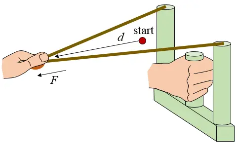
A modification of the W-shaped design is shown below. In this design the rubber bands are connected at the bottom of the frame and pulled over two rollers (or Teflon coated surfaces). The roller design is commonly shown in the JoergSprave channel. This design makes it possible for the rubber bands to have initial tension at the start position of the draw, denoted by the red dot. Furthermore, the start position of the draw can be located in the plane of the W-shaped fork, or close to it. This start position is also the approximate release position of the projectile, and given its location in the plane of the fork the projectile will be accelerated (before being released) over a greater distance than with the previous two designs. The combination of pre-tension (at the start/release position) and greater draw distance (equal to acceleration/release distance) means that the projectile will be shot with greater energy and speed than with the previous two designs.
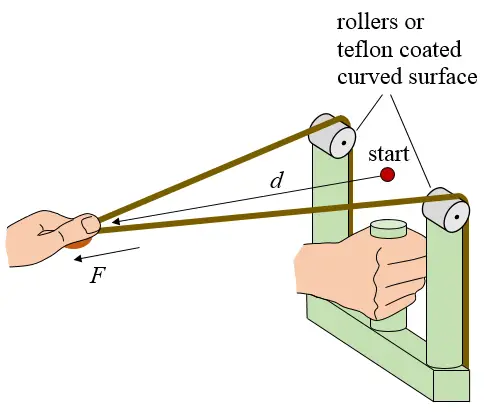
The figure below illustrates the draw force F as a function of draw distance d for this slingshot.
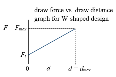
Once again, the energy stored in the rubber bands, and delivered to the projectile (assuming zero energy loss), is given by the area under the curve, which is greater than the area under the curve for the previous two designs. Assuming a linear relationship, the area under the curve is E = dmaxFi + (1/2)dmax(Fmax − Fi), where Fi is the initial pre-tension force at the start of the draw. Assuming zero energy loss, this energy is once more equal to the kinetic energy of the projectile upon release, which is given by E = (1/2)MV2.
Rollers are commonly used in the JoergSprave designs. Rollers minimize or eliminate frictional rubbing as the rubber bands ride over them (with minimal or no slipping). This is in contrast to the rubber bands riding over a rigid edge which unavoidably introduces frictional rubbing, which is a source of energy loss. However, rollers are also a source of energy loss given that the rollers are forced to rotate at high speed as the rubber bands ride over their surface when contracting (upon release). To minimize this energy loss, rollers must be used which have as little mass as possible while being strong enough during use. As an alternative to rollers one can use Teflon coated curved surfaces on the edges of the frame which the rubber bands ride over as they contract during their release. Teflon has very low friction which means that, like rollers, it will minimize energy loss as the rubber bands ride over the edge of the frame during their release. Unfortunately, in using a W-shaped design which increases draw/release length and has initial pre-tension in the bands, one must force the rubber bands to ride over the edge of the frame during release, which will cause energy loss due to either frictional rubbing or roller inertia. It is difficult to say whether using Teflon or rollers is best (i.e. results in the smallest energy loss). It is easiest to determine this by experimenting.
You can set up a simple experiment as follows. Experiment with rollers and with locked rollers (which cannot rotate) that are coated with Teflon, in order to see which results in the more powerful shot (and the smallest energy loss). First experiment with rollers. Using rollers, fire a projectile multiple times into several stacked sheets of styrofoam at point blank range, pulling back the same draw distance each time. Then measure the average penetration of the projectile into the styrofoam. Next, lock the rollers and coat them with Teflon (which can be sprayed on), and perform the same test, measuring the average penetration of the projectile afterwards. From these tests you can then determine whether the rollers or the Teflon results in the greatest penetration. This will be the best design in terms of minimizing the energy loss. If the rollers work best you can then replace them with identical rollers or simply sand away the Teflon using sandpaper. Doing the experiment this way will allow you to keep all test conditions the same, except for the variable being tested, which is the use of rollers or Teflon.
One interesting difference between the W-shaped design and the Y-shaped design is that the W-shaped design seems to have a better "feel" in the gripping hand. Someone once mentioned to me that the W-shaped design seems to exert less force on the hand, compared to the Y-shaped design, when pulling back on the rubber bands. Intrigued by this I went about trying to figure this out and it seems that the W-shape allows the gripping handle to "settle" in the hand more when the rubber bands are pulled back. It allows for a more comfortable grasp. With the Y-shaped design the top part of the handle pulls back more on the fleshy part of the hand between thumb and index finger. But with the W-shaped design the handle pushes back on the hand more evenly inside the palm. This grasping difference is due to the difference in force placement (due to the frame geometry) acting on the handle when the rubber bands are pulled back. This difference in force placement also causes the handle to bend backwards towards the slingshot operator on the Y-shaped design, and forwards away from the slingshot operator on the W-shaped design. This is illustrated in the figure below.
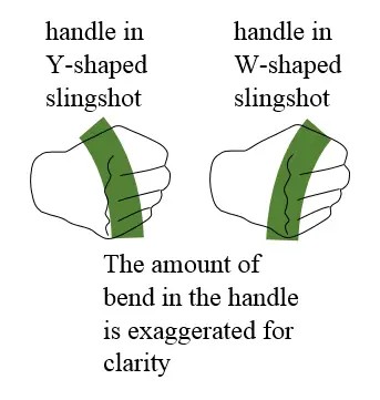
The amount of bending is likely too small to be the explanation for why the handle in the W-shaped design "settles" in the hand more than with the Y-shaped design. But it is interesting to mention nonetheless. From my analysis I concluded that the initial movement of the handle is what mainly contributes to the W-shaped design settling more in the hand than the Y-shaped design. In the Y-shaped design the top part of the handle initially moves back when pulling back on the rubber bands. In the W-shaped design the bottom part of the handle initially moves back when pulling back on the rubber bands. It is this difference in initial handle movement which is perhaps the likely reason why the W-shaped design settles more in the hand (and feels more comfortable) than the Y-shaped design.
Lastly, the fork width (representing the distance between the two rubber bands at the connection points on the slingshot frame) does not affect how much energy is delivered to the projectile upon release. When it comes to energy considerations all that matters here is the amount of draw length and the draw force. You want to maximize both during the draw, which results in the maximum kinetic energy (and speed) of the projectile after release. A reasonable design criterion is to keep the fork width as small as possible while still allowing the projectile to easily pass between the forks when shot. This will allow for a compact and easy to carry design.
Return to The Physics Of Battle page
Return to Real World Physics Problems home page